When a small robot receives a zero-speed command, its H-bridge still has to choose an electrical state. Coast leaves the motor outputs high-impedance so inertia and mechanical friction slow the rotor. Brake ties the motor terminals to the same potential, giving the generated current a low-resistance loop and producing torque that opposes rotation.
Those states can produce noticeably different stopping distance even when the firmware sets both commands to “zero.” They also change current decay and driver dissipation, so brake is not automatically the safer or more precise choice.
Read the truth table before writing the stop function
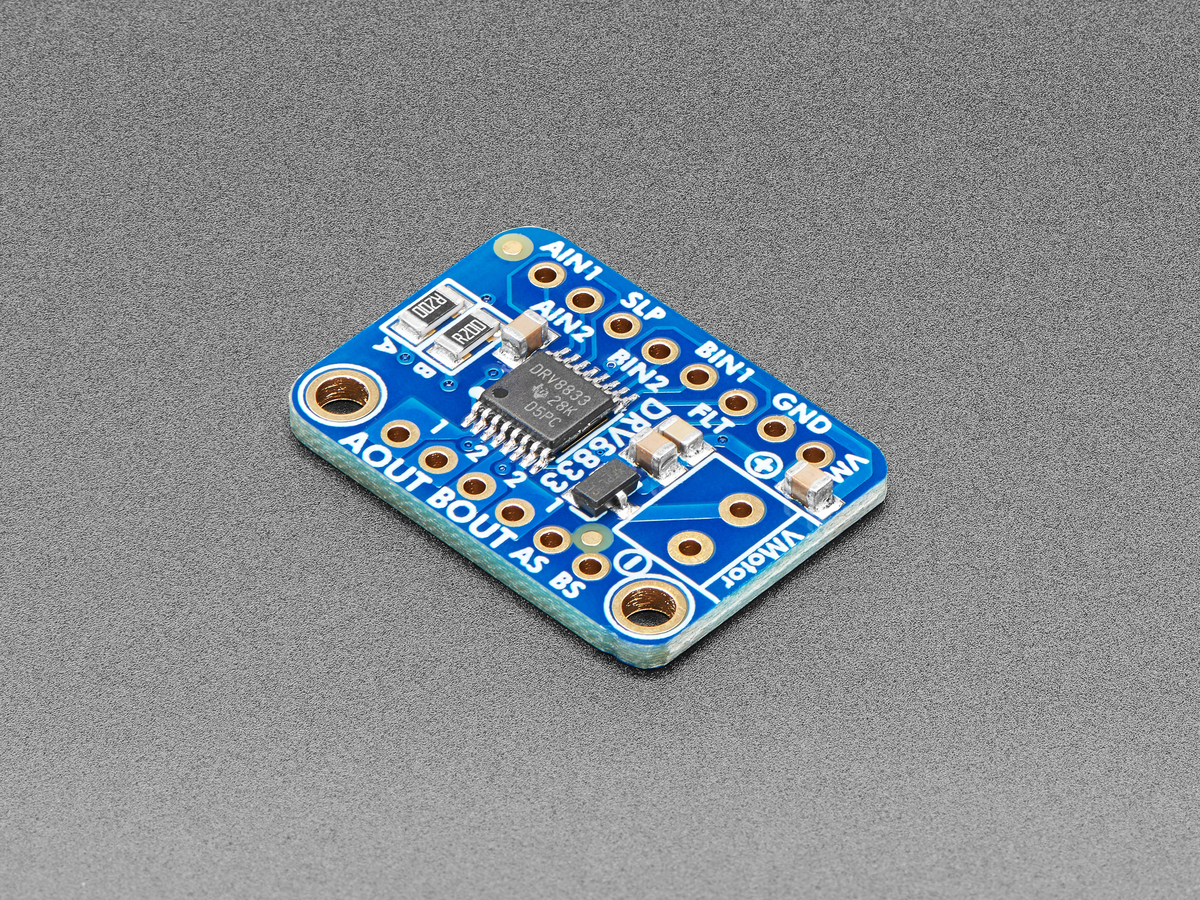
Texas Instruments’ DRV8833 data sheet maps each H-bridge input pair directly. IN1 = 0 and IN2 = 0 selects coast; IN1 = 1 and IN2 = 1 selects brake. The two opposite input states drive current in opposite directions. This makes a stop routine explicit: write both pins low for coast or both high for brake, rather than assuming a zero PWM duty cycle always selects one behavior.
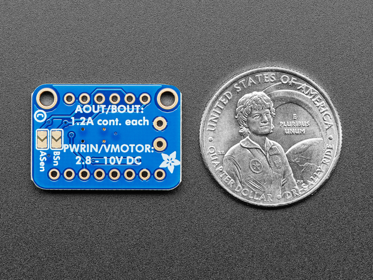
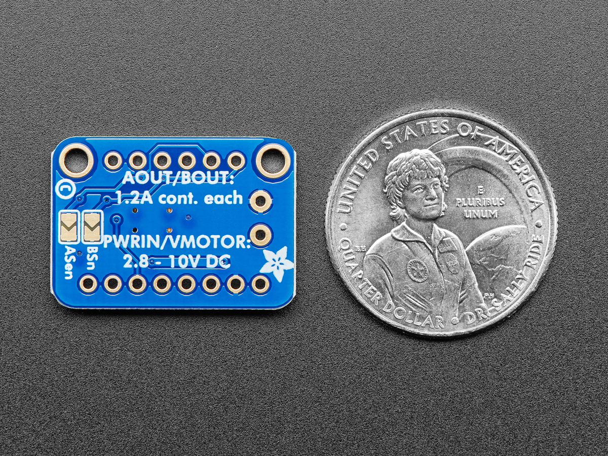
The device operates from 2.7 V to 10.8 V and is rated for up to 1.5 A RMS and 2 A peak per H-bridge under the data sheet’s thermal conditions. Those limits still require a check against motor stall current and board cooling; brake mode does not make an undersized driver acceptable.
The motor becomes a generator during deceleration
A spinning permanent-magnet motor generates back electromotive force. In coast mode the driver removes the active path, so little winding current flows and the rotor gives up energy mainly through bearing friction, gearbox losses and the mechanical load. The robot tends to roll farther, and the exact distance can vary with surface and drivetrain drag.
In brake mode the winding is placed in a closed electrical loop. The generated voltage drives current through winding resistance and the H-bridge, creating opposing torque. As speed falls, generated voltage and braking current also fall. That is why dynamic braking is strongest at higher speed and does not act like a mechanical parking brake at zero speed.
Stop mode and PWM decay are related but not identical
During PWM speed control, the bridge repeatedly alternates between drive and a recirculation state. TI’s current-recirculation note distinguishes fast decay, which reverses voltage across the winding to reduce current quickly, from slow decay, which keeps current circulating through a lower-voltage path. A driver or library may implement PWM by switching toward coast or toward brake; that choice changes current ripple, acoustic behavior and low-speed torque.
A practical control design should therefore name both behaviors. One function can define the running PWM scheme, while another defines the stopped state. Hiding both behind a single duty-cycle variable makes it easy to change braking unintentionally when a library or pin assignment changes.
Choose based on the motion requirement
- Use coast when smooth roll-down, low electrical stress and easy manual back-driving matter more than a short stop.
- Use brake when reducing stopping distance or drivetrain overshoot matters, provided the driver and supply can absorb the resulting current.
- Use closed-loop control when stopping position must be repeatable. Dynamic brake is a plant behavior, not position feedback.
On a differential-drive robot, mixing states between sides can also create a yaw impulse. Apply the same stop policy to both channels unless the turn is intentional, and keep the decision visible in code rather than relying on a library default.