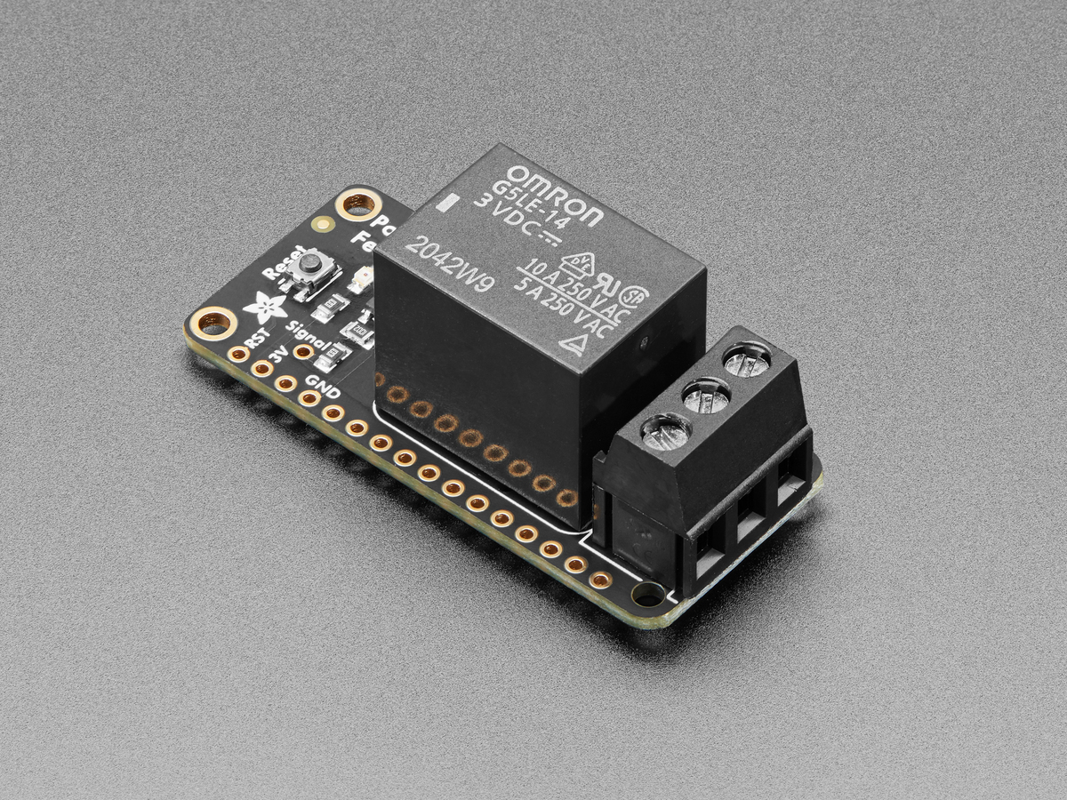
A reverse-biased diode across a DC relay coil is an effective way to protect a transistor from the coil’s turn-off spike. It also changes the relay’s mechanics: the low diode clamp lets coil current circulate for longer, so magnetic force collapses more slowly and the contacts may release later.
That tradeoff is easy to miss because a multimeter shows a healthy steady-state coil voltage. The important event occurs when the driver opens and the inductor tries to preserve current.
The spike is stored magnetic energy looking for a path
An energized coil stores energy according to E = ½LI². When the switch opens, the inductor generates whatever voltage is needed to keep current flowing, described by V = L·di/dt. Without a controlled path, that voltage can avalanche a transistor or arc across a contact.
Panasonic’s relay guidance says an unsuppressed DC inductive load can generate hundreds to thousands of volts. In its illustrated example, the unsuppressed waveform reaches 260 V. The exact spike in another circuit depends on coil inductance, current, parasitic capacitance, wiring and the switching device, so 260 V is not a universal prediction.
Why a plain diode makes release slower
A diode placed directly across a DC coil is reverse-biased while the relay is energized. At turn-off it becomes forward-biased and clamps the coil to roughly one diode drop beyond the supply rail. That low voltage protects the switch, but it also makes di/dt small. Current continues circulating through the coil resistance and diode until the magnetic field decays.
Panasonic’s automotive relay guide explicitly warns that a parallel resistor, diode or Zener diode can lengthen release time and may reduce electrical life or contribute to light welding if the application is poorly matched. The risk is load-dependent: slower contact separation can extend the time spent in an arc while current is still flowing.
A higher clamp trades voltage for speed
A diode in series with a Zener diode allows the switch node to rise to a higher controlled voltage. The larger voltage across the coil produces a larger negative di/dt, so current and magnetic force fall faster. Texas Instruments shows this diode-plus-Zener approach in its relay-coil suppression discussion.
The clamp must stay below the transistor’s safe avalanche or drain-collector voltage after accounting for supply tolerance and transients. Panasonic gives application-specific automotive guidance of at least 24 V Zener voltage for a 12 V relay rating and at least 48 V for a 24 V rating. Those are vendor recommendations for that relay context, not drop-in values for every board.
Check polarity and device ratings
- Place the suppression path physically close to the coil or driver loop to reduce wiring inductance.
- For a plain diode, Panasonic recommends reverse breakdown voltage at least 10 times circuit voltage in ordinary circuits and forward-current capability at least equal to load current.
- Confirm that a relay module does not already contain a diode, LED network or transistor driver. An internal diode makes the coil polarity-sensitive.
- Use an oscilloscope with an appropriately rated probe when release time or clamp voltage matters; a multimeter will not capture the transient shape.
For slow switching where release delay is harmless, the plain diode remains simple and robust. For contactors, valves or timing-sensitive mechanisms, choose the clamp from both sides of the problem: transistor voltage margin and acceptable mechanical release time. The protection part is not merely there to erase a spike; it sets how quickly the coil gives up its stored energy.