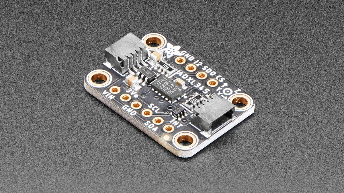
ADXL345 tap detection fails most often because firmware writes human-looking numbers directly into scaled registers. The threshold register uses 62.5 mg per least-significant bit, while duration uses 625 µs per bit. A 1.0 g threshold therefore needs a value of 16, not 1 or 1000.
The remaining work is routing: enable the intended axes, enable single- or double-tap detection, map the event to INT1 or INT2, and read the interrupt source after the pin asserts. The ADXL345 data sheet defines each of those controls separately.
Threshold and duration use different scales
THRESH_TAP at address 0x1D is unsigned with a scale of 62.5 mg/LSB. The conversion is round(threshold_g / 0.0625). A 1.5 g target becomes 24; the 8-bit maximum of 255 represents approximately 15.94 g.
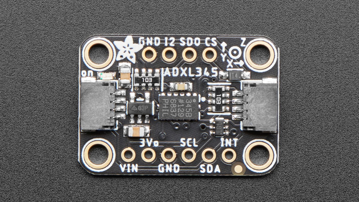
DUR at 0x21 defines the maximum qualifying tap duration at 625 µs/LSB. A 10 ms duration becomes 16. Setting duration to zero disables single- and double-tap functions, so a nonzero threshold alone cannot produce a tap interrupt.
Double tap adds latency and a second window
LATENT at 0x22 and WINDOW at 0x23 both use 1.25 ms/LSB. For example, 50 ms of latency is 40 counts, while a 300 ms second-tap window is 240 counts. A zero latency disables double-tap detection even if the double-tap interrupt bit is enabled.
The latency interval starts after the first tap ends. The window opens after latency expires, which means the second tap must occur later than the rejection interval but before the combined timing expires. Treating both registers as one delay moves the acceptance region and creates seemingly inconsistent double taps.
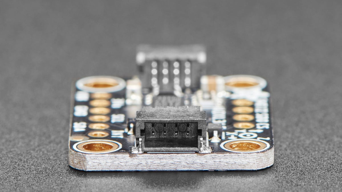
Axes, interrupt enable and pin mapping are separate
TAP_AXES selects X, Y and Z participation. INT_ENABLE enables single-tap or double-tap generation. INT_MAP then chooses the output pin: a cleared mapping bit routes that source to INT1, while a set bit routes it to INT2. Configuring only one of the three leaves the event absent or on the wrong pin.
Both interrupt outputs are active high by default and can be configured active low through the data-format register. Firmware should make the microcontroller edge and pull configuration agree with that polarity instead of assuming the breakout supplies a particular idle state.
Read the source register before changing sensitivity
When the pin asserts, read INT_SOURCE to identify whether single tap, double tap or another enabled event caused it. For tap events, ACT_TAP_STATUS reports the participating axis. That readback separates a real event routed correctly from electrical noise on the MCU pin.
Mechanical mounting changes the acceleration pulse reaching the sensor. Tune threshold and duration on the assembled project, but keep register conversion deterministic: record the desired physical units, calculate the integer code, clamp it to the 8-bit range and log the value actually written.