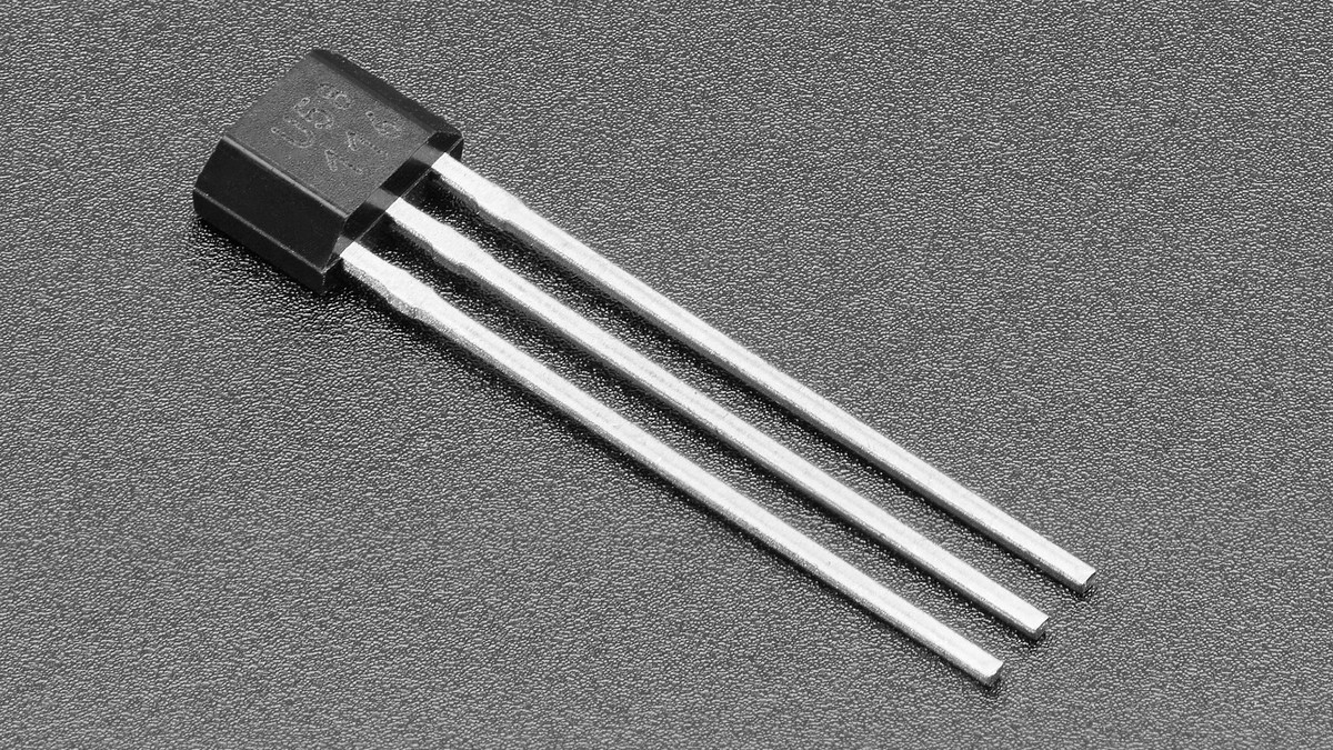
A US5881 Hall switch that never changes state may be electrically correct but missing one component: its output is open-drain. The sensor can pull the signal low when it detects the specified magnetic field, but it cannot drive the line high. A pull-up resistor to the GPIO’s logic rail supplies that second state.
The distinction matters when a 3.3 V microcontroller reads a sensor powered from another allowed voltage. Pull the output up to the logic voltage the GPIO can accept—not automatically to the sensor’s VDD—and share ground between the sensor and controller.
Prove the output stage before changing code
Melexis’s US5881 data sheet specifies an open-drain output and a 3.5 V to 24 V operating supply range. Wire VDD and ground from the package pinout, then connect OUT to the microcontroller input with an external pull-up. Adafruit’s example uses a 10 kΩ resistor; a microcontroller’s internal pull-up can also establish a high state when its value and noise margin are suitable.
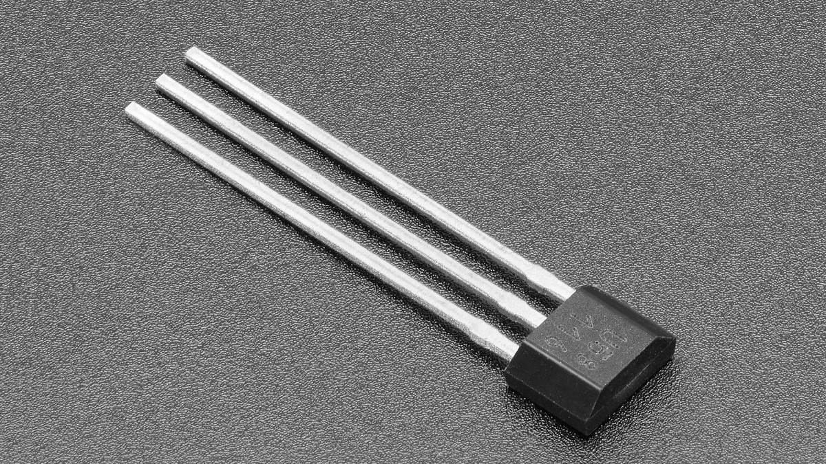
With no activating field, measure OUT relative to ground. It should sit near the pull-up rail. If it floats, the resistor or GPIO configuration is absent. If it remains near 0 V, disconnect the GPIO and check for reversed pins, a nearby magnet, a solder bridge or a damaged output before changing firmware.
Magnet orientation is part of the input
The US5881 is a unipolar switch, not an omnipolar magnetic detector. It responds to one field polarity at the sensitive face. Turning the same magnet around can therefore look exactly like a dead sensor. Adafruit’s product guidance says bringing the magnet’s south pole toward the front face makes its example output go low; package orientation must be confirmed against the data sheet rather than inferred from lead order alone.
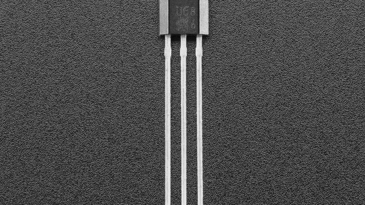
Move the magnet toward the fixed sensor while watching voltage directly. A voltmeter is enough for a slow check. If the output switches at the pin but software does not, the remaining problem is in GPIO numbering, input configuration, logic inversion or sampling—not magnetic sensitivity.
Operate and release are intentionally different
The data sheet lists a typical operate point of 25 mT and a typical release point of 20 mT, with typical hysteresis of 4.3 mT under its stated conditions. The output therefore does not chatter at one exact field value: the magnet must cross the operate threshold to switch, then fall below the lower release threshold to reset. Manufacturing tolerance, temperature, magnet grade, gap and alignment all move the physical distance at which those field thresholds occur.
That hysteresis is useful for a lid, wheel or homing sensor because small mechanical vibration near the edge is less likely to toggle the signal repeatedly. It also means a design should not set the magnet at the barely switching distance. Give the mechanism enough travel and field margin to cross both thresholds across its full tolerance and temperature range.
Use one measurement to isolate each layer
- Output never reaches high: verify pull-up voltage, resistance, shared ground and pinout.
- Output is always high: reverse the magnet, reduce the air gap and verify the sensitive face.
- Voltage switches but code does not: check GPIO selection, input mode and active-low logic.
- Reading chatters near one position: add mechanical field margin before adding software debounce.
The US5881 can operate from a wide sensor supply, but the logic interface remains simple: OUT is only a controlled path to ground. Once the pull-up creates a valid high level, magnet polarity and field strength can be diagnosed separately instead of being mixed with firmware guesses.