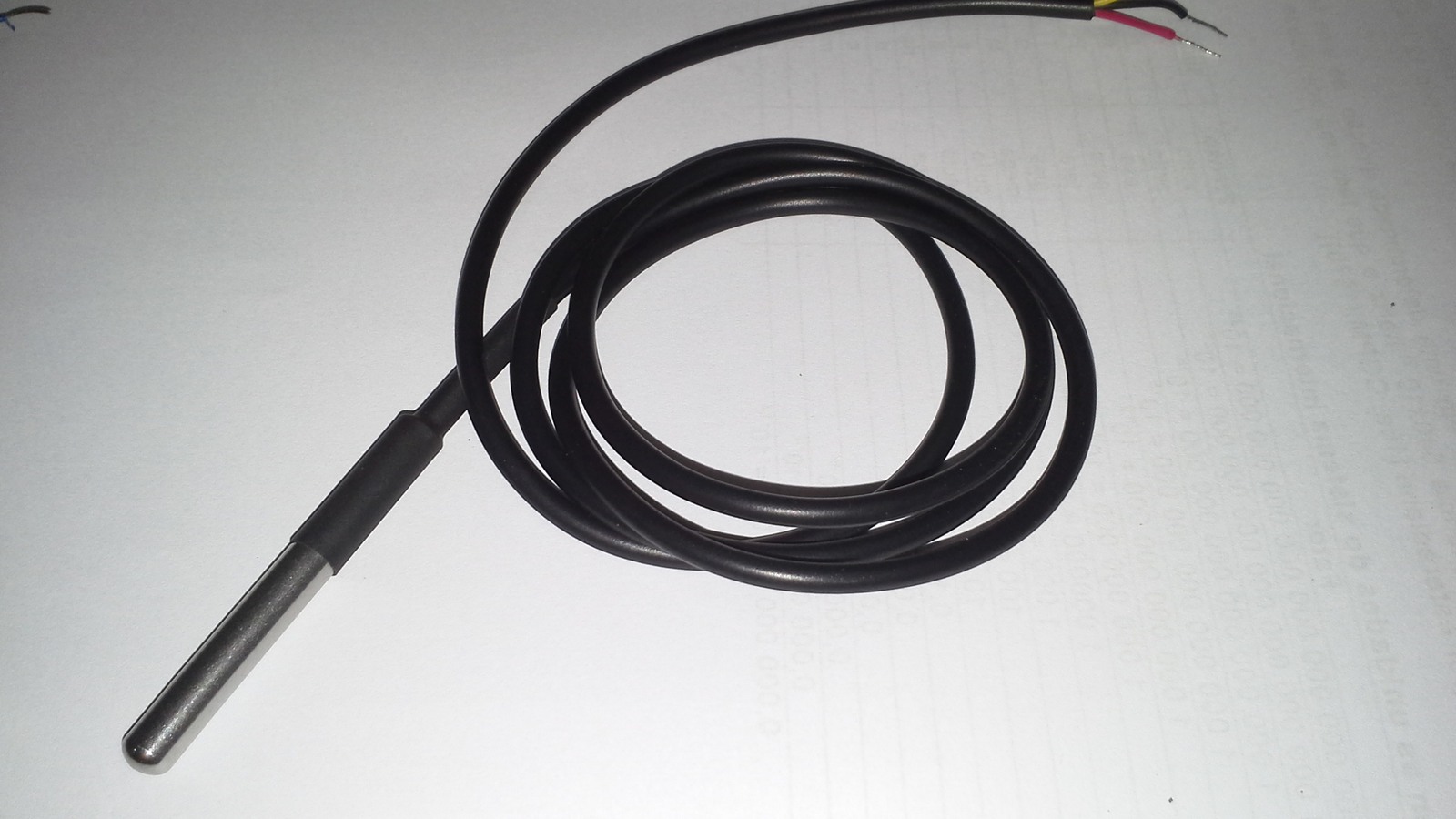
A DS18B20 that repeatedly reports exactly 85°C may be returning its power-on register value, not measuring a hot sensor. The datasheet defines +85°C as 0x0550 in the temperature register after reset. Confirm that a conversion completed and that the scratchpad CRC passes before replacing the probe.
This distinction matters because “85°C” and “bad CRC” are different observations. One can be validly transmitted stale reset data; the other says the received scratchpad bytes failed integrity checking. Treating both as a dead sensor hides power, timing and 1-Wire signal faults.
Start with the power-on value, not the converted value
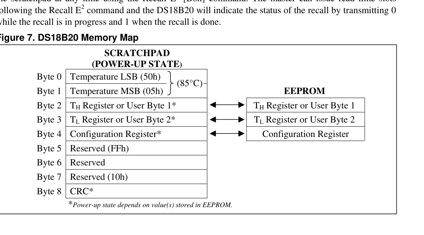
The DS18B20 stores temperature as a signed 16-bit value in scratchpad bytes 0 and 1. At power-up those bytes are 0x50 and 0x05, or 0x0550 little-endian. At 12-bit resolution the least significant bit represents 0.0625°C, so 0x0550 equals 1360 × 0.0625°C = 85°C.
A normal acquisition issues Convert T (command 0x44), waits for conversion to complete, and then reads the scratchpad. Maximum conversion time depends on resolution: 93.75 ms at 9 bits, 187.5 ms at 10 bits, 375 ms at 11 bits and 750 ms at 12 bits. Code that resets the device, reads immediately or removes power before completion can keep seeing the reset value.
Use the ninth byte to decide whether the bus read is trustworthy
The scratchpad is nine bytes long. Bytes 0 and 1 carry temperature; bytes 2 through 4 carry alarms and configuration; bytes 5 through 7 are reserved; byte 8 is the CRC over bytes 0 through 7. The datasheet specifies the polynomial CRC = X8 + X5 + X4 + 1. Accept the temperature only when the recalculated CRC matches byte 8.
On Linux, the w1_therm driver exposes this evidence in the w1_slave file. Its first line contains the nine hexadecimal bytes, the calculated CRC and YES or NO. The second line reports the retained data and temperature. Kernel documentation notes that when a new CRC fails, the driver retains the previous valid value. A monitoring program that parses only t= can therefore miss a fresh read failure.
Parasite power changes the timing and current boundary
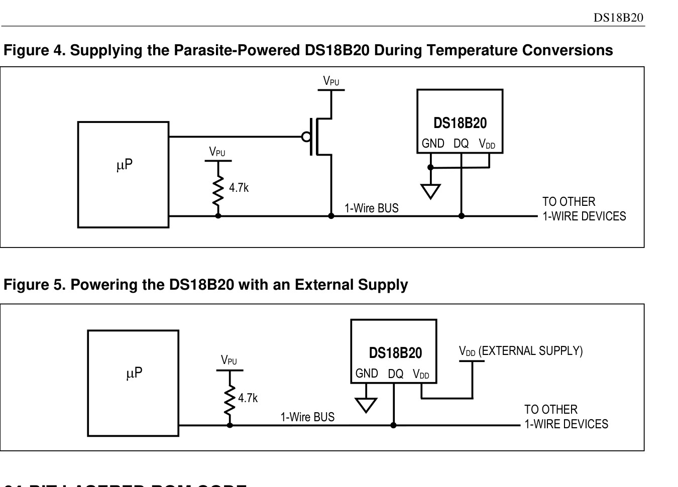
The device can run from 3.0 V to 5.5 V on VDD or draw parasite power from the DQ line. The familiar 4.7 kΩ pull-up is a weak bus pull-up; during conversion, a parasite-powered DS18B20 can draw up to 1.5 mA. The datasheet requires a strong pull-up to be applied within 10 µs after Convert T or Copy Scratchpad and held for the operation.
If the controller cannot provide that strong pull-up, use the three-wire external-supply arrangement where the probe and installation permit it. External VDD also lets the bus carry other traffic while conversion proceeds. The datasheet does not recommend parasite power above +100°C because leakage can prevent reliable communication.
Read one sensor at a time before blaming the whole bus
Each DS18B20 has a 64-bit ROM code with family code 0x28. On a multidrop bus, log the ROM ID beside every CRC and value so one marginal spur does not look like a network-wide failure. Start with a short cable and one known sensor; then add branches and probes while watching CRC results rather than temperature alone.
For a Linux node, capture the complete w1_slave output several times. An exact 85°C with YES immediately after reboot points toward an absent or unfinished conversion. Repeated NO points toward wiring, pull-up, power or timing integrity. A device directory that disappears entirely moves the fault earlier, toward reset/presence detection or the master interface.
A compact diagnosis sequence
- Record ROM ID, all nine scratchpad bytes and the CRC result.
- Issue Convert T and wait for the configured resolution’s maximum time.
- Read again; reject the sample if byte 8 does not match the calculated CRC.
- If parasite powered, verify the strong pull-up path and its timing; otherwise verify VDD at the sensor under conversion load.
- Reduce the bus to one short branch, then restore cable length and additional sensors incrementally.
The key is not to label 85°C as a generic error code. It is a documented register state. Once conversion completion and CRC are logged separately, the remaining fault usually falls into one of three boundaries: software sequencing, conversion power or 1-Wire signal integrity.