A 5 V UART transmitter should not drive a 3.3 V-only receiver until the receiver’s absolute and recommended input limits are known. The signal direction matters: the 5 V device’s TX line is the hazardous path into the 3.3 V RX input, while a 3.3 V TX output may already meet the 5 V receiver’s high-level threshold—or may not.
Featured image: Adafruit.
Treat each wire as a one-way electrical interface. UART labels describe the transmitter and receiver at each endpoint; connect TX to RX and RX to TX, then translate only the directions whose voltage limits require it. A shared ground is still required so both endpoints interpret the same signal voltage.
Start with the receiver, not the nominal rail
For each direction, read the transmitting output-high minimum and the receiving input-high minimum, then read the receiver’s maximum permitted input voltage. A 3.3 V output is safe into a 5 V input only if it reaches that input’s guaranteed high threshold. A 5 V output is safe into a 3.3 V input only if the input is explicitly 5 V tolerant or the signal is shifted.
Do not use the absolute-maximum rating as an operating target. It marks a damage boundary, not a level that guarantees long-term operation or a valid logic state.
A divider can protect one receive direction
For a push-pull 5 V TX feeding one 3.3 V RX, a two-resistor divider can reduce the high level. The unloaded relationship is Vout = Vin × Rbottom / (Rtop + Rbottom). With 10 kΩ on top and 20 kΩ to ground, a 5.0 V high becomes about 3.33 V.
Vout = 5.0 V × 20 kΩ / (10 kΩ + 20 kΩ)
Vout ≈ 3.33 V
That is a one-way solution. It does not actively raise a 3.3 V TX signal for the opposite receiver, and the resistor values combine with input and wiring capacitance to slow the edge. Verify the waveform at the intended baud rate rather than assuming any ratio is sufficient.
A BSS138 board is convenient, but not universal
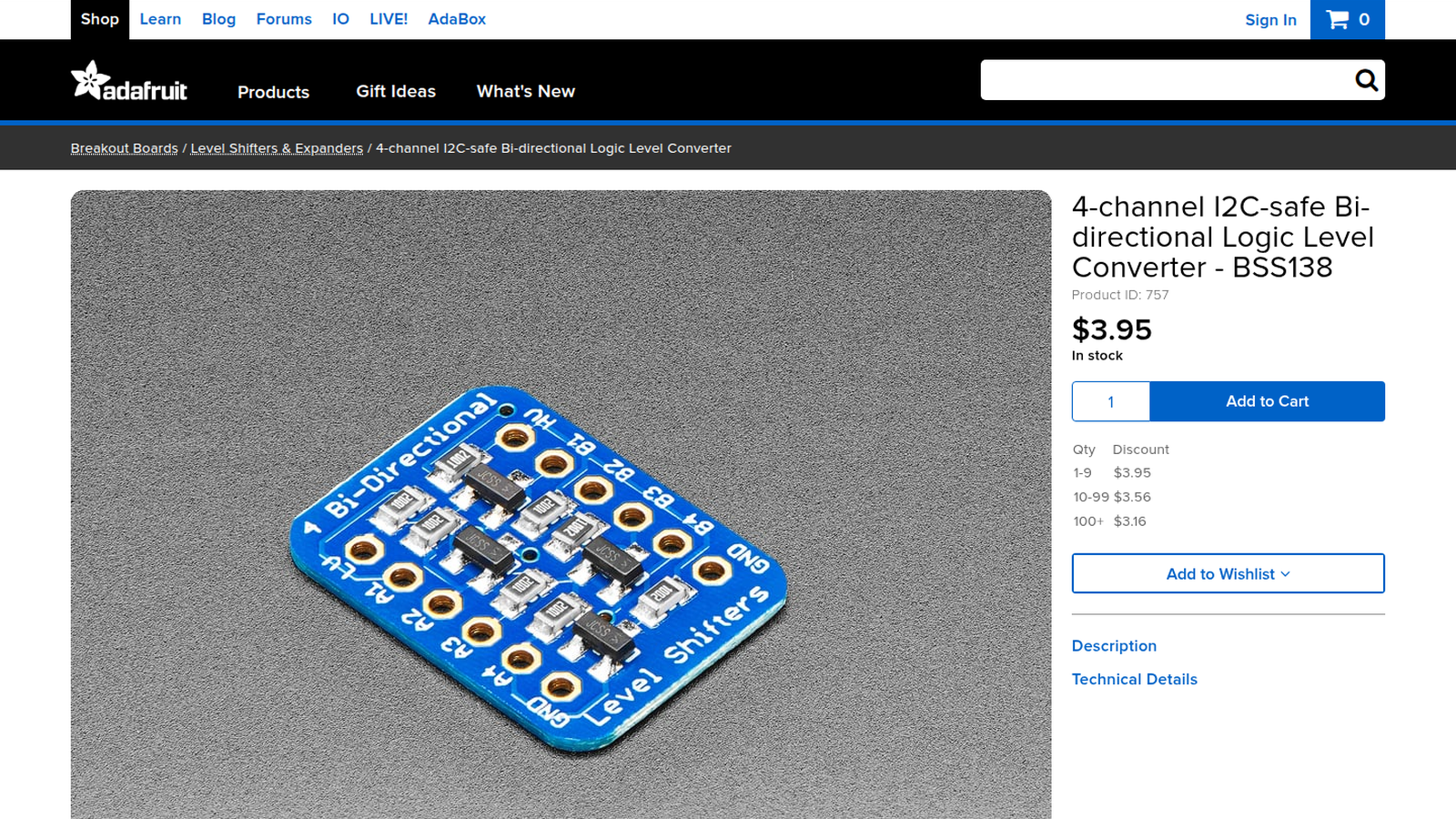
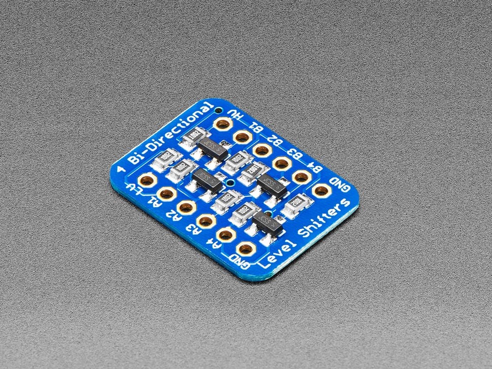
Adafruit’s four-channel BSS138 converter supports low-side rails down to 1.8 V and high-side rails up to 10 V. Its product documentation says it can handle TTL serial and slow SPI below 2 MHz, while warning that the onboard 10 kΩ pull-ups make it more sluggish than a push-pull translator.
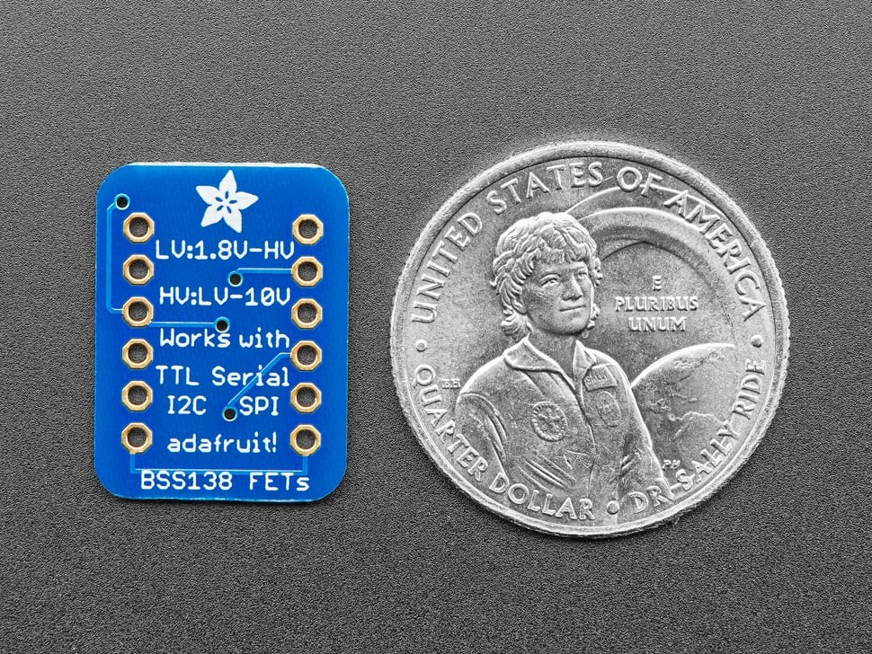
The BSS138 topology was designed around open-drain interfaces such as I²C. It can be useful for modest UART rates, but a direction-controlled or auto-direction push-pull translator is a clearer choice when edge rate, cable capacitance, or high baud rate matters. Check that any auto-direction device supports the load and signal behavior; translator families have different drive and direction rules.
Verify the link in a fixed order
- Confirm TX crosses to RX and both grounds are connected.
- Measure idle-high voltage at each receiver.
- Check the receiver’s recommended thresholds and maximum input rating.
- Capture a repeated byte at the receiver pin and inspect amplitude and edge shape.
- Only after the electrical layer is valid, match baud, data bits, parity, and stop bits.
If the voltage is correct but characters are nonsense, use the separate unknown-baud recovery workflow. If the USB adapter changes its device path between boots, assign a stable Linux udev name. Those solve different layers from an over-voltage or threshold mismatch.
The decisive calculation is per direction: protect the lower-voltage receiver, confirm that the return signal clears the higher-voltage receiver’s threshold, and keep the translator’s speed and topology inside their documented range.