If the controller resets exactly when a hobby servo starts, reverses, or hits a load, check the power path before rewriting the PWM. Adafruit warns that servos powered from an Arduino 5 V pin can introduce electrical noise and brownouts that make the board reset or behave erratically.
Featured image: Pololu.
The command signal may be perfectly valid while the shared rail collapses. Even micro servos can draw several hundred milliamps in motion, and some high-torque units exceed 1 A under load. A regulator that powers the controller comfortably at idle can still fall below the controller’s brownout threshold during acceleration or stall.
Trace three conductors, not one PWM wire
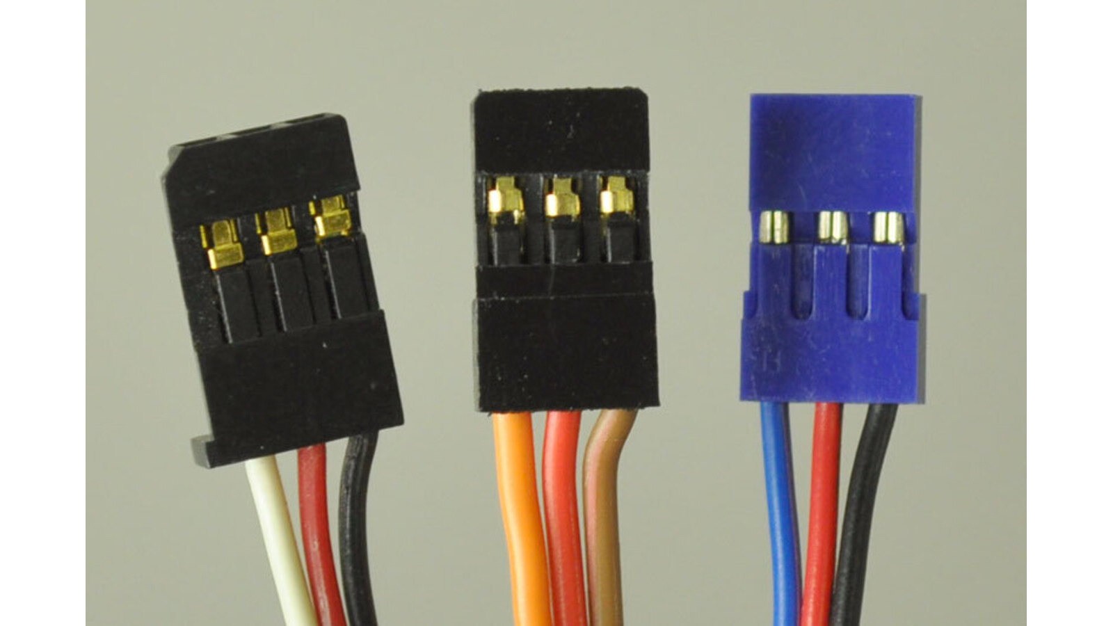
A conventional servo cable carries ground, supply, and signal. Pololu notes that the supply conductor is normally in the center, while ground and signal colors vary among black/white, brown/orange, and black/blue conventions. Reverse power can destroy a servo, so verify the connector rather than trusting color alone.
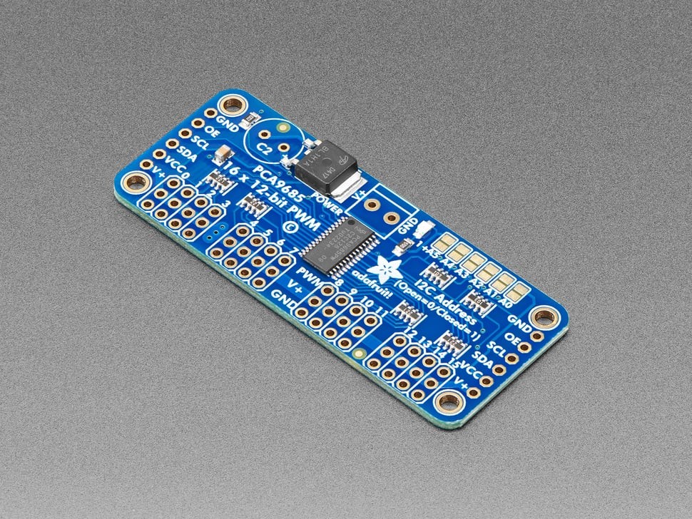
On the PCA9685 breakout, VCC powers the control electronics; V+ powers the servo headers. Supplying VCC does not supply the motors. A separate 5–6 V servo source should feed V+, while the controller, driver, and servo supply share a ground reference so the PWM voltage has a defined return.
Measure the rail at the event that causes the reset
- Command one unloaded servo through a small movement and watch the controller rail.
- Repeat during the direction change or mechanical load that triggers the fault.
- Measure near the controller and near the servo distribution point; a difference implicates wiring, connector, or trace resistance.
- Compare the lowest observed controller voltage with its documented brownout threshold.
A multimeter may average over a short dip. An oscilloscope can reveal whether the rail falls for milliseconds as the motor current rises. Probe against the controller ground at the board; measuring only at the bench supply can miss voltage lost in cables and connectors.
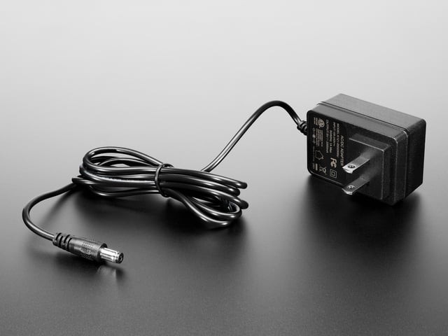
Size the source for motion, not idle
Pololu distinguishes quiescent current from stall current: real operating current falls between them and changes with load and activity. Use a documented stall or peak figure when available, then consider how many servos can start or reverse together. Do not add individual stall currents blindly when motion is sequenced, but do not size from idle current either.
Adafruit suggests n × 100 µF as a starting bulk-capacitance estimate on its PCA9685 board—at least 470 µF for five servos—while explicitly noting that there is no universal value. Capacitance can soften a brief dip; it cannot compensate for an undersized source, thin wiring, or a servo held at stall.
Only then return to the pulse
If the rails remain inside limits and the controller does not reset, verify pulse width and endpoints with the separate PCA9685 timing calculation. If unrelated sensors corrupt as servos move, use the broader power-rail noise workflow.
The decisive split is observable: a reset accompanied by rail sag is a power-distribution problem; motion error on a stable rail points back toward signal timing, endpoint calibration, mechanics, or a damaged servo.