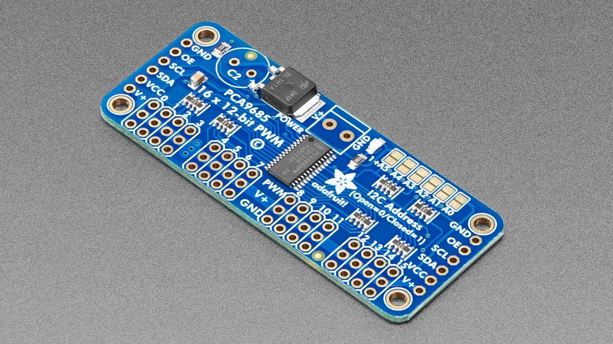
A PCA9685 does not store a servo command in microseconds. Each channel stores rising and falling edges inside a 4096-count PWM frame, so the correct count depends on the frame’s actual frequency. At exactly 50 Hz, a 1.5 ms pulse is about 307 counts—not a universal magic number.
Featured image: Adafruit.
The conversion comes directly from the NXP PCA9685 timing model:
count = pulse_us × frequency_hz × 4096 ÷ 1,000,000
The result is an initial timing value. It does not by itself establish a safe mechanical endpoint or prove that the board’s internal oscillator matches its nominal frequency.
Calculate from the frame period
A 50 Hz PWM signal repeats every 20 ms, or 20,000 µs. Dividing that period by 4096 gives 4.8828125 µs per count. The common 1.0, 1.5 and 2.0 ms pulse widths therefore map to 204.8, 307.2 and 409.6 counts. Rounded starting values are 205, 307 and 410.
If the configured frequency is 60 Hz instead, the frame is 16,666.7 µs and each count spans about 4.069 µs. The same 1.5 ms pulse then needs roughly 369 counts. Copying the 50 Hz value would shorten the pulse to about 1.25 ms.
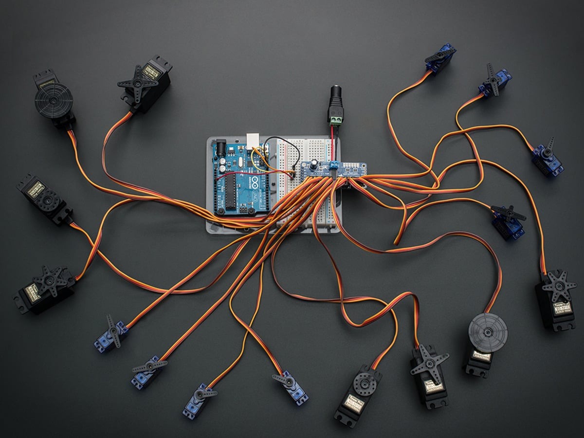
One prescaler sets the frequency for every channel
The PCA9685 has 16 independent 12-bit channels, but they share one PWM frequency. A board can assign different edge counts to each servo, yet it cannot run one channel at 50 Hz and another at 300 Hz at the same time. Mixed loads must accept the same frame rate or use separate controllers.
NXP specifies a programmable range of roughly 24 to 1526 Hz. The prescaler is derived from the oscillator clock, 4096 counts and the desired update rate. Libraries normally hide that register calculation, but the physical output still depends on the clock value they assume.
Calibrate frequency before trimming endpoints
The internal oscillator is nominally 25 MHz, and real boards can deviate enough to shift the output period. Measure one PWM channel with a scope or logic analyzer after calling the frequency-setting function. If a requested 50 Hz frame measures 47 Hz, calculations made with 50 Hz will not produce the intended pulse width.
Adafruit’s library exposes setOscillatorFrequency() and documents that the stored frequency is a calibration value; the chip does not introspect its own oscillator. Enter the measured or corrected clock value before calling setPWMFreq(), then verify the frame again.
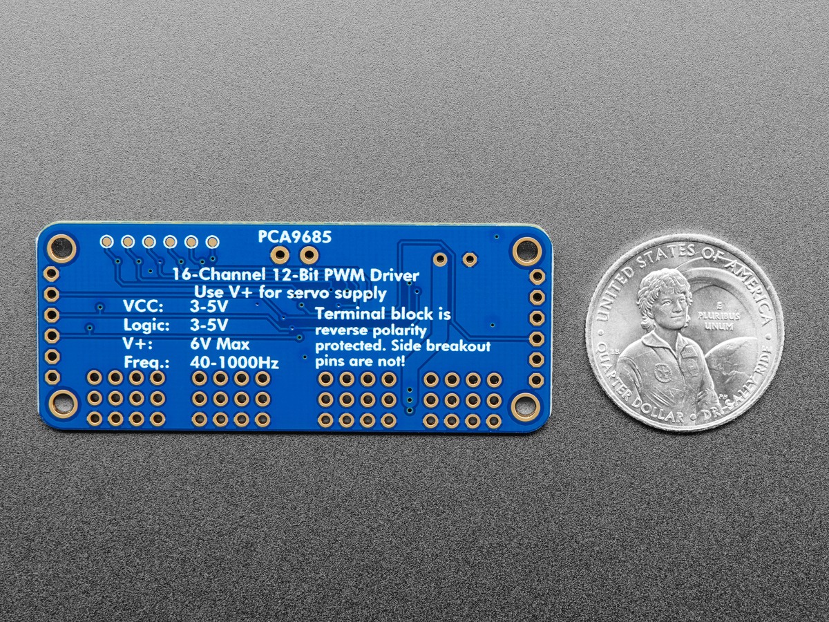
Servo endpoints are a separate mechanical limit
After timing is correct, begin near the servo’s neutral pulse and expand the range gradually. Stop before buzzing, stalled motion or linkage binding. A data sheet or vendor example may use about 1–2 ms, but individual models and mechanisms can require narrower limits.
Power integrity is another separate boundary. Servo current comes from the V+ rail, not from the PCA9685 logic supply. A correct pulse count cannot prevent resets or twitching caused by a collapsing servo supply or a missing common ground. Likewise, TVG’s TB6612FNG control-state guide shows why a valid PWM signal does not establish that the power stage is enabled.
The practical order is frequency, microseconds-to-count conversion, measured pulse verification and only then mechanical endpoint trimming.