An AS5600 angle stream that jumps or freezes should be checked against the sensor’s magnetic-status signals before any smoothing is added. The device can report whether a magnet is detected and whether the field is too weak or too strong; those states identify geometry problems that a digital filter cannot repair.
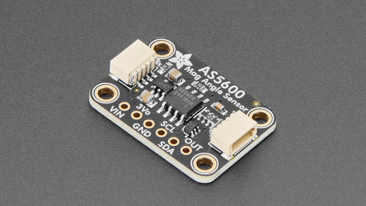
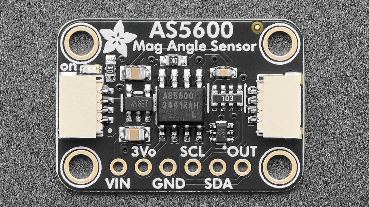
The Adafruit AS5600 guide exposes those checks directly and reports raw and scaled angle as 12-bit values. Start by logging status, angle and magnitude together while rotating the magnet slowly.
Establish a valid magnetic field first
The magnet must rotate around the sensor’s center with its north-south axis oriented correctly. Adafruit specifies sensing up to about 3 mm from the chip body and recommends a diametrically appropriate rare-earth magnet. A magnet displaced sideways can produce a changing field magnitude even if the shaft itself rotates smoothly.
Use the magnet-detected state as the first branch. If detection is false, verify polarity orientation, centering and distance. If the sensor reports maximum-gain overflow, the field is too weak; minimum-gain overflow indicates a field that is too strong. Move or remount the magnet before interpreting the angle trace.
Do not mistake 12-bit wraparound for a jump
The raw angle spans 0 through 4095 for one revolution. One count is therefore 360 / 4096 = 0.087890625°. A transition from 4090 to 5 is a normal crossing through zero, not a reverse movement of 4085 counts.
For signed motion, subtract consecutive samples and unwrap the difference into the interval from -2048 to +2047 counts. That preserves direction across zero. Filtering the raw 0–4095 sequence without circular arithmetic can create a false midpoint near 180° whenever samples straddle zero.
Confirm the interface and output mode
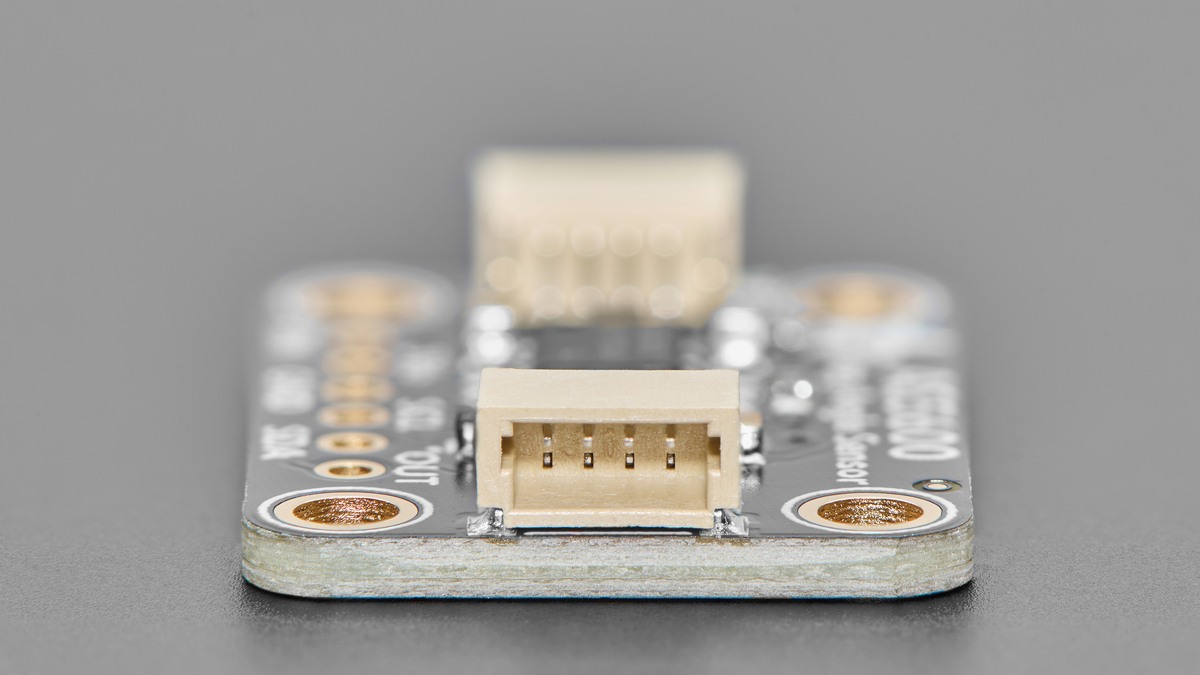
The breakout’s fixed I²C address is 0x36. Its SCL and SDA lines include 10 kΩ pull-ups and accept 3–5 V logic through the board. A successful scan confirms bus addressing, but it does not prove that the magnet is valid.
The OUT pin can represent angle as analog voltage or PWM. In full-range analog mode, approximately 0 V corresponds to 0° and VDD to 360°; PWM maps the same span into duty cycle. Firmware that assumes analog while the device is configured for PWM will read pulse edges as noise.
Only after status remains valid through a full turn should filtering enter the diagnosis. At that point, compare raw angle, scaled angle and the unwrapped count delta. A discontinuity that coincides with weak/strong status is mechanical or magnetic; a discontinuity with stable status is more likely sampling, wrap handling or output-mode interpretation.