An RFM69 wire antenna needs a frequency-specific starting length: about 17.3 cm for 433 MHz or 8.2 cm for 915 MHz in free space. Those numbers come from one quarter of the wavelength, L = c / (4f), using the exact speed of light and the intended center frequency.
They are starting dimensions, not guaranteed installed resonance. The breakout’s feed point, nearby ground and wiring, enclosure material and conductor thickness all alter the electrical length. The first hard requirement is simpler: use the antenna for the module’s actual band.
Calculate before cutting
NIST defines the speed of light as exactly 299,792,458 m/s. At 433 MHz, 299,792,458 / (4 × 433,000,000) equals 0.1731 m. At 915 MHz, the same calculation gives 0.0819 m. Rounded for workshop use, those are 17.3 cm and 8.2 cm.
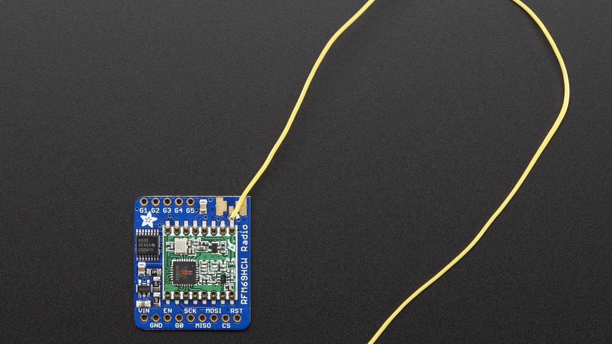
A velocity factor below 1 shortens the resonant conductor relative to the free-space value, but a bare wire monopole near a small board does not have one universal correction factor. Cutting substantially short removes tuning margin. A safer prototype starts near the calculated value and trims only with a repeatable return-loss, field-strength or packet-link measurement.
The antenna must match the radio variant
The RFM69HCW family covers multiple sub-GHz bands, but a specific module and matching network are sold for an intended range. Adafruit’s product 3071 is the 433 MHz breakout; its 868/915 MHz counterpart is a different product. Setting a 433 MHz board to a 915 MHz frequency in software does not transform its RF matching network or antenna.
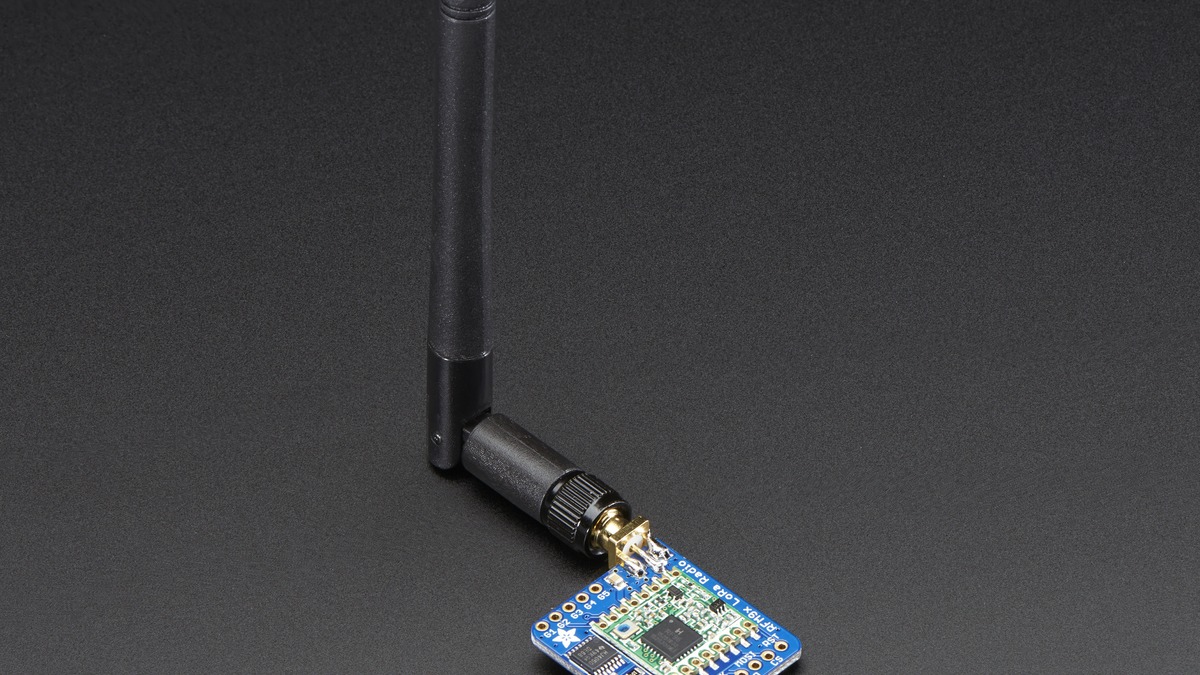
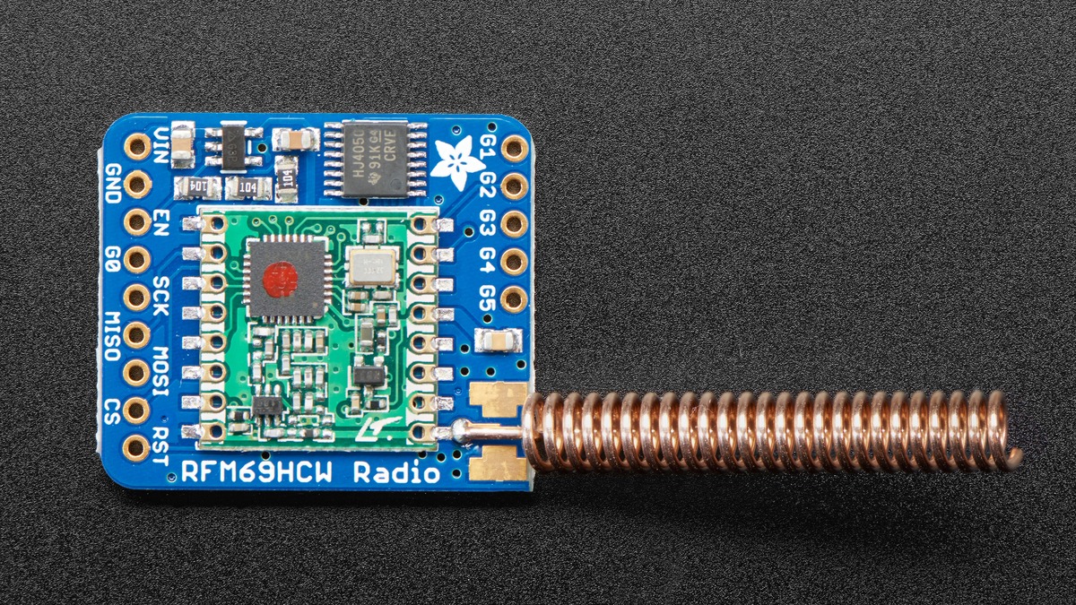
The breakout exposes three antenna approaches: a soldered wire, a u.FL connector or an edge-launch SMA connector. Use one feed path, not multiple antennas in parallel. An unpopulated connector footprint is not an active second antenna, but a wire left attached while an SMA antenna is connected creates an uncontrolled branch at the feed.
Ground and enclosure are part of the result
A quarter-wave monopole works against a return path. On a compact controller, the PCB ground, battery cable and connected wiring become part of that RF structure. Folding the antenna along the ground plane, placing it against a battery or enclosing it beside a metal panel can detune the system even when the wire length is mathematically correct.
Keep the radiator away from noisy digital wiring and high-current motor leads. Route the first section consistently between prototypes, and compare received signal strength only with the same transmit power, packet settings, orientation and distance. An RSSI improvement from changing two variables at once does not identify which antenna change helped.
Transmit power does not repair a mismatched antenna
The RFM69HCW data sheet specifies a high-power amplifier capable of up to +20 dBm under its supported configuration. Raising power increases current and regulatory exposure; it does not restore energy reflected by a poor impedance match. Use the lowest power that meets the link requirement after the antenna and installation are stable.
Frequency, output power, bandwidth and duty cycle must also comply with the rules for the operating location. A quarter-wave calculation answers the physical starting length only. It does not authorize a frequency or transmit-power setting.