A 555 timer in monostable mode produces one output pulse after a trigger. The familiar estimate t ≈ 1.1RC is a nominal value, not a promise: resistor tolerance, capacitor tolerance, leakage and the trigger waveform all move the observed interval.
Where 1.1RC comes from
After TRIG falls below roughly one-third of VCC, the output goes high and the discharge transistor releases the timing capacitor. The capacitor charges through R toward VCC. The pulse ends when THRES reaches approximately two-thirds of VCC.
The charging equation is VC = VCC(1 − e−t/RC). Setting VC to 2VCC/3 cancels the supply term: t = −RC ln(1 − 2/3) = RC ln(3), or about 1.099RC. The common 1.1 multiplier is therefore the rounded result of the timer’s threshold ratio.
For R = 100 kΩ and C = 10 µF, the nominal interval is 1.1 × 100,000 × 0.000010 = 11.0 seconds. The units matter: ohms multiplied by farads produce seconds.
Budget the range, not only the center
Suppose the resistor is ±5% and the capacitor is ±20%. A simple worst-case part-value budget uses both low limits and both high limits. The short end is 11.0 × 0.95 × 0.80 = 8.36 seconds. The long end is 11.0 × 1.05 × 1.20 = 13.86 seconds.
That spread exists before timer threshold error, temperature drift, dielectric behavior or leakage are added. Large electrolytic capacitors often have wider tolerance and more leakage than small film or ceramic parts. For a classroom delay, the range may be acceptable. For a precise interval, select tighter components or move the timing function to a crystal-clocked counter or microcontroller.
Long delays expose leakage
Increasing R reduces the charging current. At the start of the 100 kΩ, 10 µF example on 5 V, the resistor current is 50 µA. Near the two-thirds threshold it has fallen to about 16.7 µA. Capacitor leakage, board contamination and input current become a larger fraction of that current as R grows.
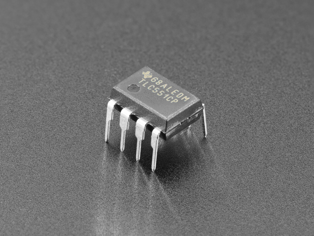
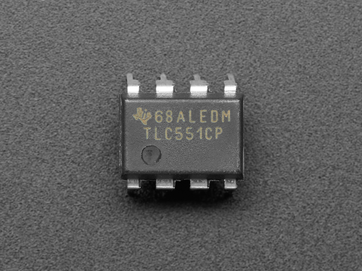
If leakage approaches the available charging current, the capacitor rises more slowly than the ideal equation predicts or may never reach threshold. That is why making R enormous is not a free way to obtain hours of delay. A CMOS timer such as the TLC551 reduces input-current demands, but the capacitor and board still have real leakage.
Make the trigger unambiguous
The trigger must fall below about one-third VCC and then return high. A switch can bounce across the threshold, while a trigger held low longer than the intended interval can prevent a clean one-shot result. Use a defined pull-up and ensure the source meets the timer’s input limits.
RESET overrides the other inputs, so it should not float. The control-voltage pin can alter the one-third and two-thirds thresholds; if it is not being used for modulation, follow the device data sheet’s bypass guidance and keep noisy wiring away from the timing node.
Choose a standard capacitor first, solve R = t ÷ (1.1C), and reject impractically high resistance before committing to parts. Then calculate the low and high intervals from actual tolerance values. If the trigger comes from a mechanical contact, TVG’s switch-debounce guide explains when an RC network, Schmitt trigger or software filter is the better tool.