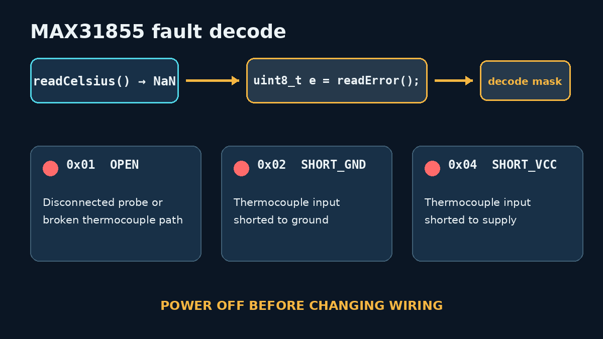
A NaN from an Adafruit MAX31855 temperature read means the converter reported a fault, but it does not tell you which fault until the low three bits are decoded. The quickest useful next step is therefore readError(), not swapping the thermocouple at random: 0x01 means open circuit, 0x02 means short to ground, and 0x04 means short to VCC.
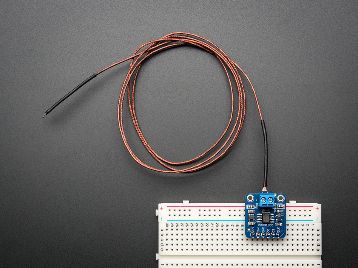
Featured image: Adafruit.
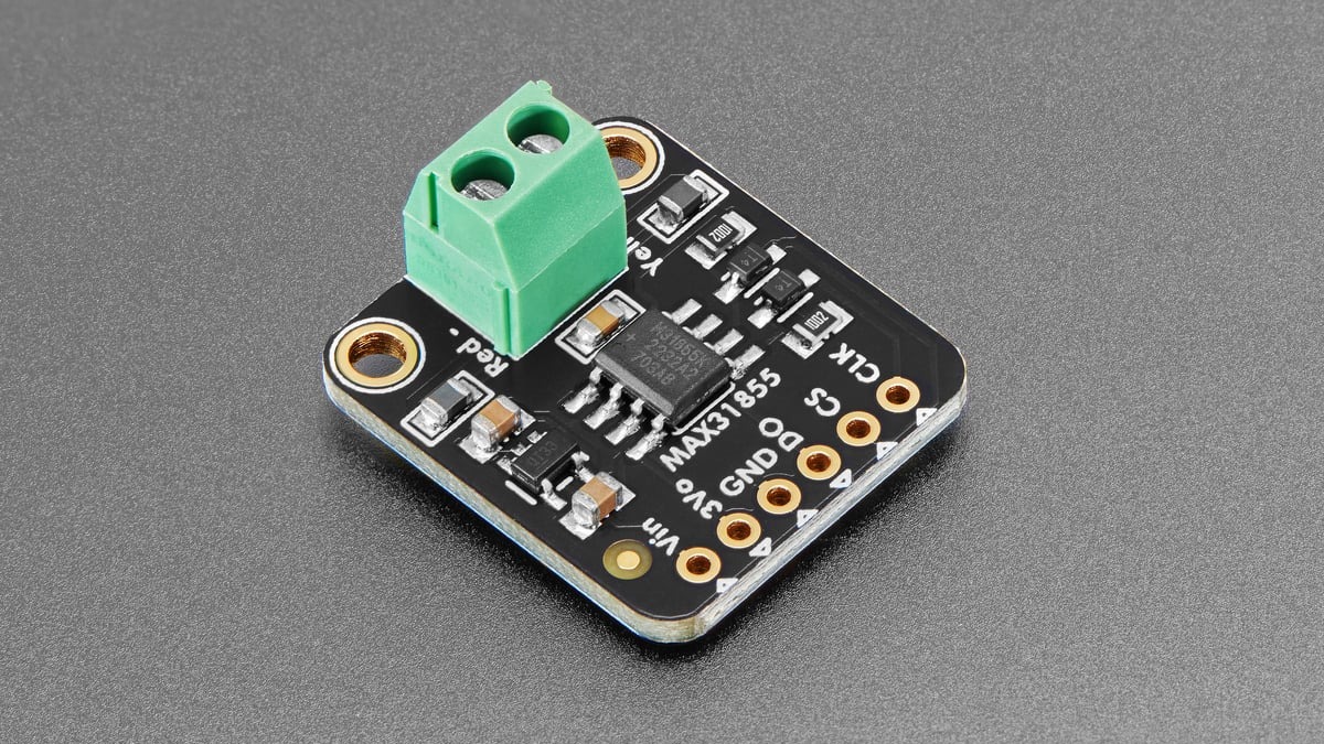
The MAX31855 returns a 32-bit, read-only SPI frame containing thermocouple temperature, internal cold-junction temperature and fault status. In Adafruit’s driver, readCelsius() checks the enabled fault mask and returns NAN when any selected fault is active. The separate error call reads the same interface and masks the result with 0x07, preserving the three diagnostic bits.
Print the error mask while the fault is present
Adafruit’s MAX31855 library defines MAX31855_FAULT_OPEN as 0x01, MAX31855_FAULT_SHORT_GND as 0x02 and MAX31855_FAULT_SHORT_VCC as 0x04. Its example sketch branches on all three after detecting isnan(c). More than one bit can be set, so code should use bitwise checks rather than assume the result is one exclusive value.
double c = thermocouple.readCelsius();
if (isnan(c)) {
  uint8_t e = thermocouple.readError();
  if (e & MAX31855_FAULT_OPEN)      Serial.println("Open thermocouple");
  if (e & MAX31855_FAULT_SHORT_GND) Serial.println("Short to ground");
  if (e & MAX31855_FAULT_SHORT_VCC) Serial.println("Short to VCC");
}
Capture that value before disturbing the wiring. An intermittent open can disappear when a terminal is touched, while a whisker or shield contact can move when the enclosure is opened. Logging the raw mask alongside time and temperature makes a sporadic fault much easier to correlate with vibration, cable movement or heater switching.
What each bit narrows down
Open circuit, 0x01: the measurement path through the thermocouple is broken. A loose screw terminal, broken probe junction, damaged extension wire or disconnected plug can all produce this result. With power removed and the thermocouple isolated from the board, continuity across the probe can reveal a complete break. A low resistance is normal for many thermocouples; it is not evidence that the sensor is a resistor-type temperature probe.
Short to ground, 0x02: one of the thermocouple inputs is being pulled to circuit ground. Check for stray strands at the terminal block, a grounded metal sheath, contact between the probe and a grounded chassis, or an unintended common connection through other equipment. A grounded-junction thermocouple can be unsuitable when the measurement circuit expects an isolated junction.
Short to VCC, 0x04: an input is coupled to the supply rail. Inspect adjacent header pins, solder bridges, damaged cable insulation and any external connector that also carries power. The MAX31855 datasheet defines these faults at the thermocouple inputs; the bit does not identify the physical location of the short.
Confirm the interface before blaming the probe
The Adafruit breakout uses a three-signal SPI connection: serial clock, chip select and data out from the converter. The current library constructs its SPI device in mode 0 at 1 MHz. Because the MAX31855 is read-only, there is no MOSI line. A wrong chip-select pin, missing ground or a bus-level wiring error can corrupt communication even when the thermocouple itself is intact.
Check the board supply and common ground, then confirm that chip select reaches the intended module. If several converters share clock and data, each requires its own chip select. Also confirm that the code and hardware target the MAX31855 rather than the older MAX6675: Adafruit notes that the two are not pin- or code-compatible drop-in replacements.
The two temperatures have different meanings
The converter reports the thermocouple channel in 0.25 °C increments and its internal reference-junction channel in 0.0625 °C increments. The internal reading is the board-side temperature used for cold-junction compensation; it is not a second measurement of the remote probe tip. A plausible internal reading beside a faulted thermocouple reading can show that the chip is responding even though the external measurement path is bad.
After repairs, power the system normally and require several fault-free conversions before trusting control logic again. If the application drives a heater, a NaN should put the output into a defined safe state rather than leave the previous command latched. Similar open-versus-short reasoning applies to resistance sensors, but the thresholds and conversion behavior differ; TVG’s guide to open, short and sensor-curve thermistor faults covers that separate case.