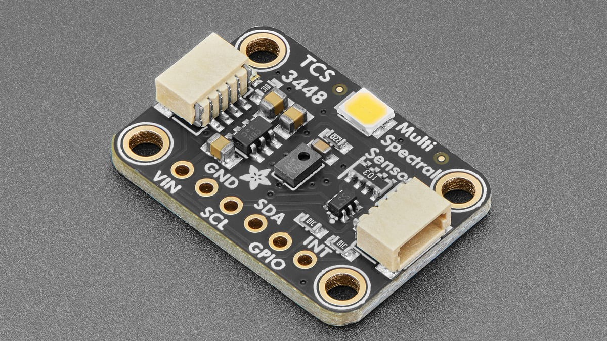
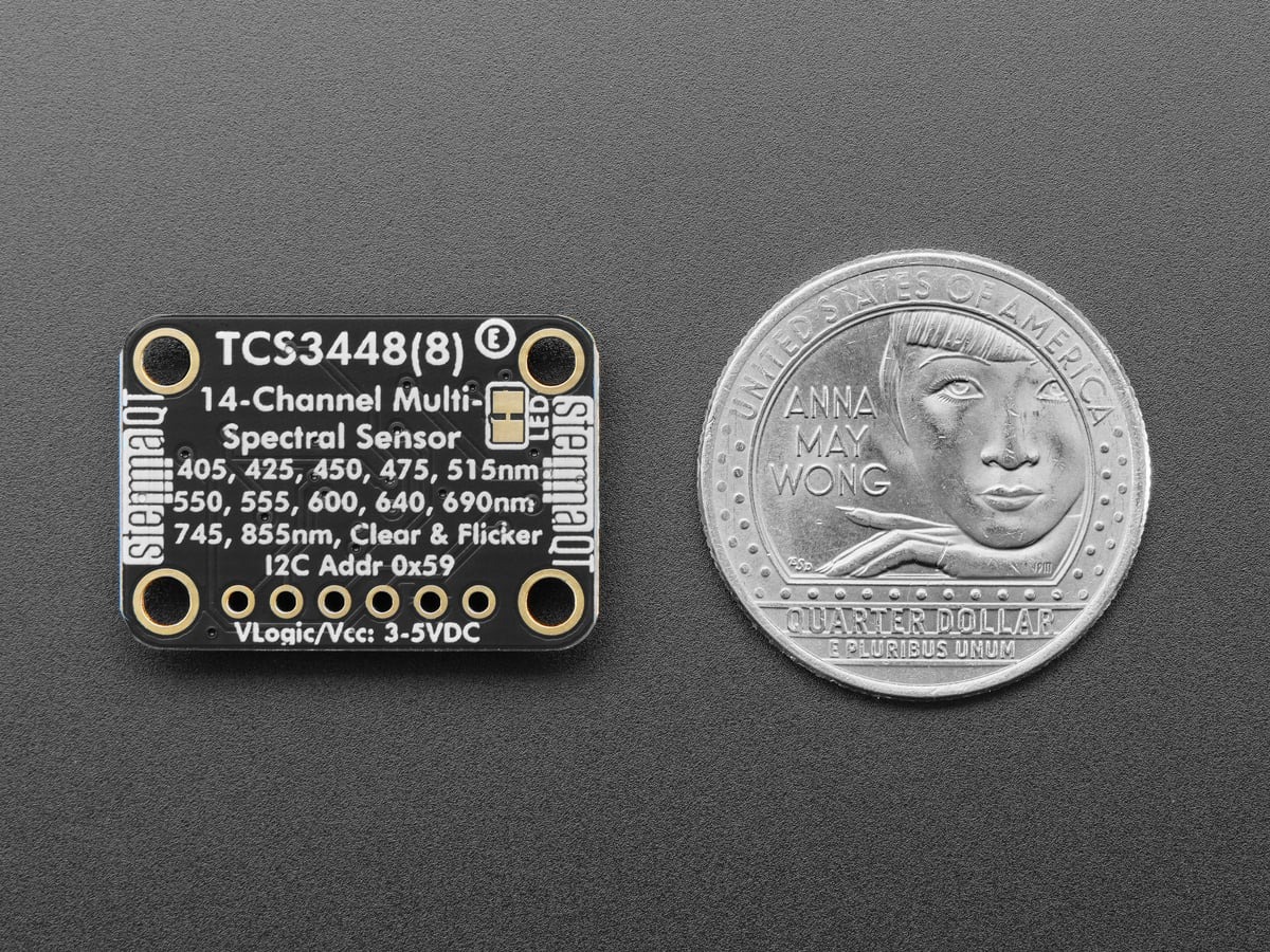
Adafruit has released a breakout for the ams OSRAM TCS3448, a 14-channel spectral sensor that adds more wavelength detail than a basic RGB color sensor. The useful migration detail is smaller but consequential: the new device uses the fixed 7-bit I²C address 0x59, so firmware written for the related AS7343 at 0x39 will not find it without a driver change.
Featured image: Adafruit.
The product listing describes 11 overlapping visible-light bands, a near-infrared channel, a clear channel and a dedicated flicker channel. Adafruit specifies the visible channels across roughly 380 to 800 nanometers and flicker detection up to 1 kHz. That makes the board relevant to projects that need to distinguish lighting spectra, evaluate emitted or reflected color, or recognize modulation that a conventional lux sensor would collapse into one number.
Independent eeNews Europe coverage of a flicker-capable multispectral ambient-light sensor explains that lighting-frequency data can help cameras choose exposure timing and avoid banding under LED sources. That context illustrates the value of a dedicated flicker channel without changing the TCS3448-specific limits documented by Adafruit and ams OSRAM.
Four more channels do not make it a drop-in AS7343 replacement
Adafruit calls the TCS3448 an ams OSRAM refresh of the AS7343 and says the two parts share a register map. The new Adafruit TCS3448 Arduino library, version 1.0.0, reflects that relationship by subclassing the existing AS7343 driver. Register compatibility saves software work, but the changed address still means an old sketch cannot simply keep its previous probe address.
The practical fix is to use a TCS3448-aware driver or explicitly change the address in code where the underlying library permits it. Builders should also check the complete bus before adding the board: because the TCS3448 address is fixed, a second device already occupying 0x59 requires an I²C multiplexer or a separate bus rather than an address jumper.
The library returns raw spectral data, not finished color measurements
The sensor uses 25 photodiodes and routes the measurements through six independent 16-bit ADCs, according to Adafruit’s product documentation. Its automatic sensor multiplexer, or SMUX, produces 18 result slots across three cycles. The library’s readData() method starts at the status register and reads status plus 36 data bytes as one coherent 37-byte frame, keeping gain, saturation state and channel values tied to the same measurement.
That distinction matters in logging code. The library documents the result values as raw 16-bit ADC counts—not lux, irradiance or gain-normalized intensity. Comparing two materials or lamps therefore requires a controlled geometry, consistent integration time and gain, and attention to saturation. A larger count is not automatically a calibrated statement about absolute optical power.
The included basic example configures 64× gain, ATIME=29, ASTEP=599 and the 18-channel SMUX mode before printing 12 spectral results plus a broadband visible result. Those settings are a runnable starting point, not universal measurement settings. Bright sources can saturate at high gain; dim scenes can disappear into noise when integration is too short.
Board-level integration is aimed at maker hardware
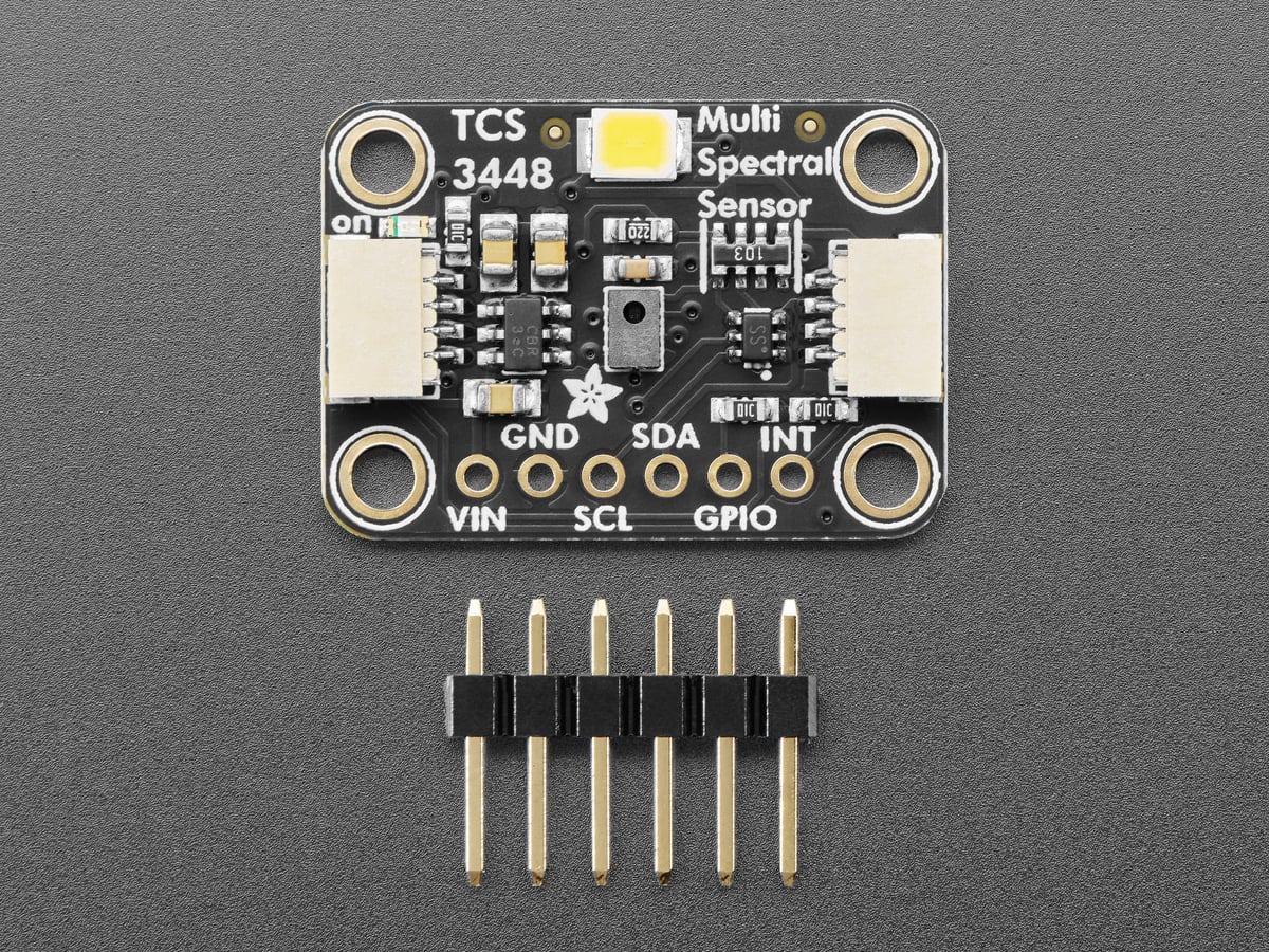
Adafruit’s board adds a 3.3-volt regulator and level shifting so it can connect to 3.3 V or 5 V microcontrollers. Two STEMMA QT/Qwiic connectors provide solderless power and I²C, while the breakout pads expose VIN, ground, SDA, SCL, interrupt and GPIO. The onboard white LED can illuminate a nearby target for reflective measurements, but a fixed illumination geometry is still necessary if readings must be compared over time.
The board reduces wiring work; it does not eliminate optical design. Sensor angle, distance, ambient spill, target texture and the LED spectrum can all change the counts. For bus-level problems, the same electrical checks in TVG’s I²C sensor wiring and dropout guide still apply. For an AS7343 migration, however, the first software checkpoint is unambiguous: scan for 0x59, load the TCS3448 driver, and treat its spectral output as raw data until the project supplies its own calibration.