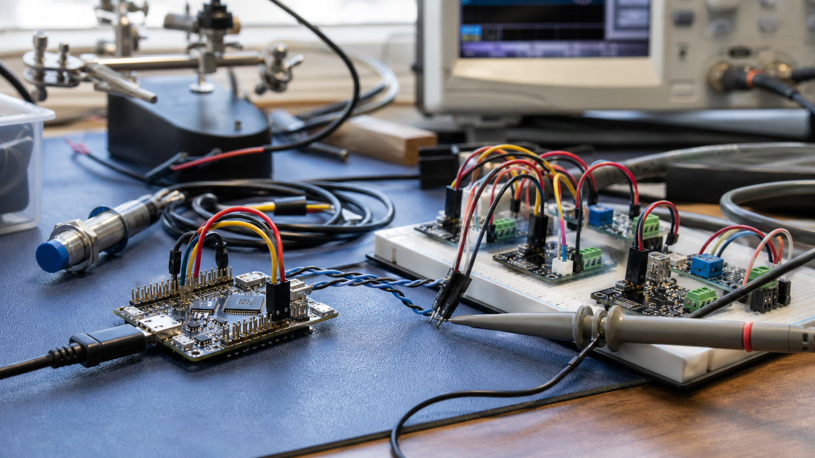
Editorial mode: Analysis / Guide. I2C is one of the first buses many students use because it makes sensors feel easy: two signal wires, power, ground and a library call. On a moving robot, that simplicity can be deceptive. A sensor that works on a desk can drop out when the cable gets longer, the battery sags, motors switch, or another board adds different pull-up resistors.
The NXP UM10204 I2C-bus specification remains a core reference for how the bus works, including timing and electrical behavior. Adafruit’s I2C learning guide is a practical maker-oriented introduction. TVG’s takeaway for robots is straightforward: I2C is excellent inside a compact electronics bay, but it is not a magic field wiring standard.
The quick answer
Keep I2C runs short, share a solid ground, verify voltage levels, avoid stacking too many pull-ups, slow the bus when needed, and use a logic analyzer when dropouts become intermittent. If a sensor must be far from the controller, consider a different bus, a local microcontroller, or an I2C extender designed for that job.
What usually goes wrong
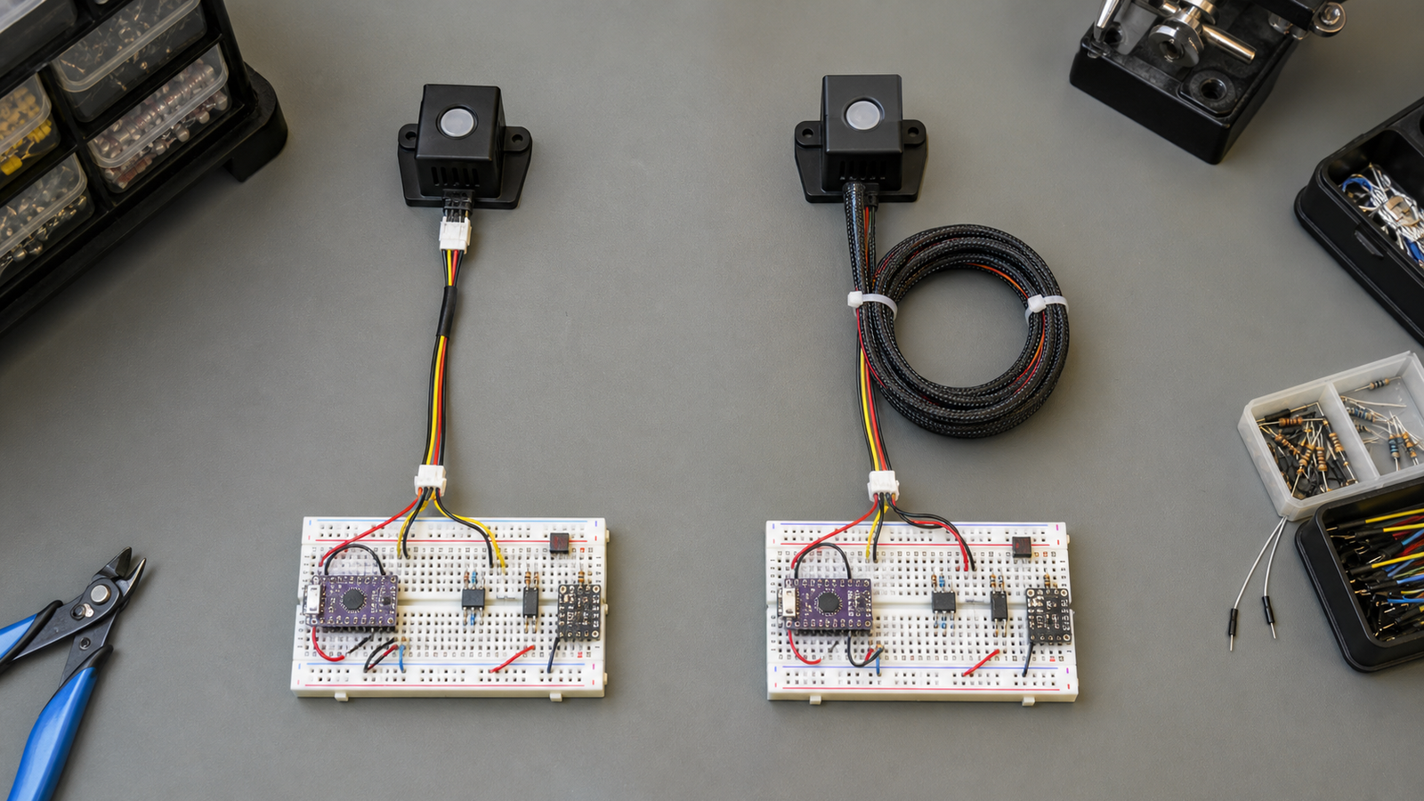
The first failure is cable length. I2C was designed for short board-to-board communication, not long harnesses running past motors and power wiring. Long leads add capacitance, pick up noise and make edges slower. A sensor may pass a five-minute bench test and still fail during a match, demo or classroom run.
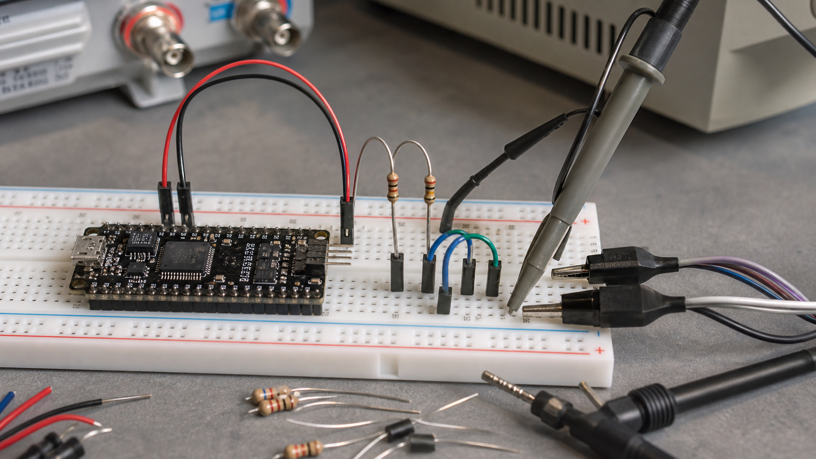
The second failure is pull-up confusion. Many breakout boards include pull-up resistors. Several boards on the same bus can make the effective resistance too low, increasing current and distorting behavior. Removing or changing pull-ups is not glamorous, but it is often the difference between a stable robot and a ghost fault.
The third failure is level mismatch. A 5 V microcontroller, 3.3 V sensor and mixed breakout board can appear to work until tolerances, cable losses or startup order expose the problem. Use level shifting when required, and do not assume a module is safe just because it survived one test.
Maker-lab checklist
- Test the sensor on the actual cable length and route before mounting it permanently.
- Keep sensor wires away from motor leads, high-current LED wiring and switching regulators.
- Confirm every device address and document address changes in the code repository.
- Count pull-ups across the whole bus, not one board at a time.
- Try a slower bus speed before replacing random parts.
- Add local strain relief so movement does not become an electrical problem.
TVG Take
I2C is a great teaching bus because it exposes the boundary between software convenience and electrical reality. The best robot teams do not abandon it; they keep it in the right place, test it with the real harness, and escalate to better physical-layer choices when the robot layout demands it.
Sources and related reading
- UM10204 I2C-bus specification and user manual
- Adafruit: Working with I2C Devices
- TVG: CAN Bus in Robotics
Related TVG reading
For more engineering-first context, compare this piece with Arducam PiNSIGHT Spec Review: A Raspberry Pi AI Camera Worth Testing, LooperRobotics Insight 9 Project Watch: A Spatial AI Camera Backer Checklist, Camera Sensor Sizes for Creator and Maker Vision: What Actually Matters.