A MAX31865 temperature error that is smooth and repeatable often starts with the conversion constant, not the RTD. The chip digitizes the ratio of RTD resistance to an external reference resistor, so firmware must use the resistance actually fitted to the board.
On Adafruit’s breakouts, the PT100 version uses a 430 Ω reference and the PT1000 version uses 4.3 kΩ. Swapping those constants moves the calculation by a factor of ten before the temperature equation is even applied.
Verify the resistance ratio first
The MAX31865 provides a 15-bit conversion result plus a fault bit. For a non-faulted sample, the underlying resistance is approximately RRTD = ADCcode × RREF ÷ 32768. At 0°C, an IEC PT100 is near 100 Ω and a PT1000 is near 1000 Ω; a result far from that scale is easier to diagnose as a ratio or wiring error than as a mysterious temperature offset.
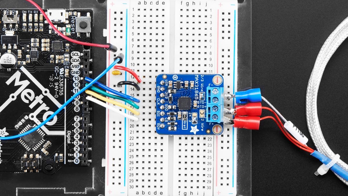
Read the reference-resistor marking or the breakout documentation instead of copying a library default. The reference tolerance also matters: Adafruit specifies a 0.1% reference resistor on its board, while the MAX31865 data sheet attributes system sensitivity to the external resistor. Calibration cannot rescue a constant that names the wrong component value.
Lead resistance depends on the selected wire mode
A 2-wire RTD puts both lead resistances in series with the sensing element. A few ohms of cable can therefore look like a real temperature increase. Adafruit notes that meter-long leads may contribute 1 Ω, 2 Ω or even 4 Ω and can create roughly half to a full degree Celsius of error in its example.
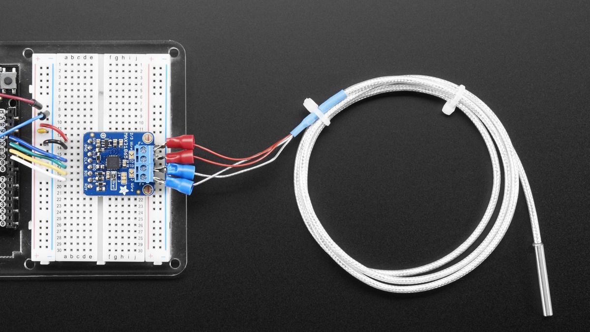
A 3-wire connection estimates and compensates lead resistance when the paired leads are closely matched. A 4-wire connection separates force and sense paths, removing lead voltage drop from the resistance measurement. The hardware mode, terminal placement and software’s 3-wire configuration bit must agree.
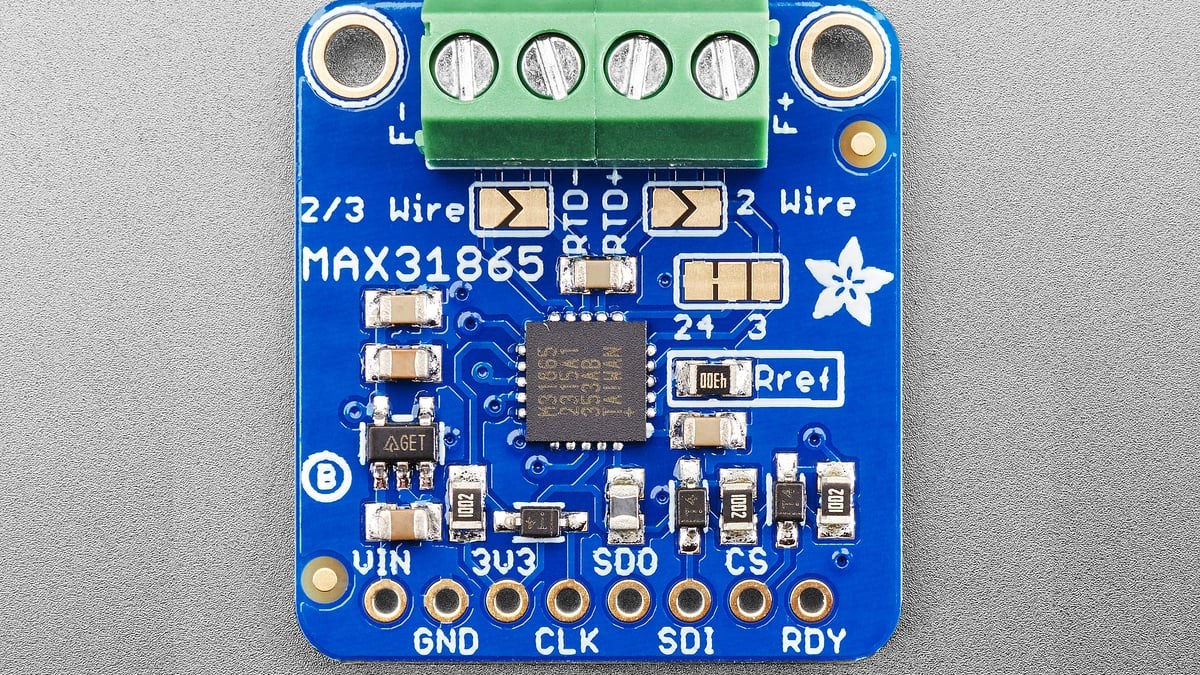
On the cited Adafruit board, four-wire use is the default. Three-wire use requires changing the labeled jumpers, while two-wire use bridges each terminal pair. A library call that selects three-wire compensation cannot correct a breakout still strapped as four-wire, and a three-wire probe attached to the wrong terminals defeats the intended symmetry.
Use the fault register before adding offsets
The MAX31865 includes programmable detection for open RTD leads, shorts across the RTD and shorts to supply or ground. Its inputs are protected against faults as large as ±45 V, but protection is not a substitute for reading the fault status. Log the raw ADC word and fault register together so an intermittent connector is not converted into a plausible temperature.
The data sheet specifies a 21 ms maximum conversion time. In one-shot operation, wait for the conversion to complete before reading; otherwise repeated reads can return an older sample. Continuous operation simplifies timing but increases how long bias remains applied to the RTD.
Diagnose in resistance units
Disconnect power and confirm the probe resistance with a meter at a known ambient condition. Then check the board’s fitted reference, jumper state and terminal mapping. With power restored, capture the raw code, computed resistance and fault bits before converting resistance to temperature.
If the resistance is correct but the temperature is not, inspect the Callendar–Van Dusen coefficients and nominal RTD type. If the resistance itself is wrong, stay with reference, leads and hardware mode. That boundary prevents a software offset from hiding a physical wiring defect.