A TCS34725 can return different RGB values for the same object when the lamp, distance, angle, gain or integration time changes. The sensor measures red, green, blue and clear light; it does not remove the optical setup from the measurement.
For repeatable readings, fix the geometry and illumination first. Then read raw RGBC values, choose gain and integration time with headroom below saturation, and only afterward calculate ratios or display colors.
Stabilize the light path before tuning registers
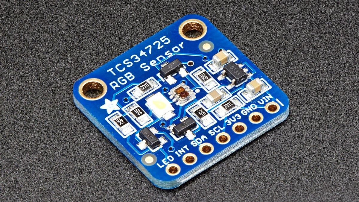
Reflected-color measurements depend on both the sample and the light reaching it. Hold the sensor at a fixed distance and angle, shield it from changing room light and use the same illuminator for every sample. Adafruit’s breakout includes a nominal 4150 K white LED that can be switched, but ambient light can still change the result if the fixture is open.
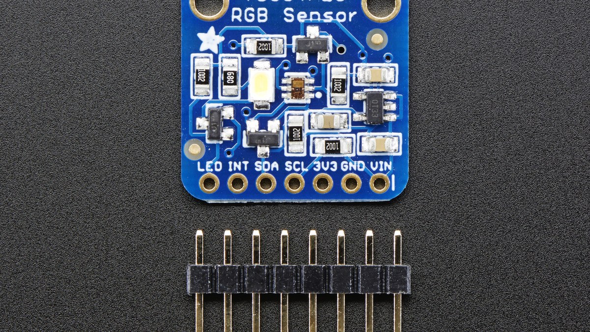
A simple dark reference with the illuminator off reveals enclosure leakage and electronic offset. A stable white reference reveals changes in lamp output, geometry or contamination. Those references are more informative than assigning color names to one unverified RGB tuple.
Use the clear channel as an exposure check
The TCS3472 family integrates all four channels simultaneously into 16-bit results. The data sheet gives a 0-to-65,535-count ADC range at a 153.6 ms integration setting. If the clear channel or any color channel sits near the ceiling, ratios become unreliable because one or more channels may be clipped.
Reduce gain first when a bright target saturates across practical integration times. The supported gain settings are 1×, 4×, 16× and 60×. For dim scenes, more gain raises signal but also magnifies noise and offset; a longer integration can improve collected signal at the cost of slower updates and greater sensitivity to motion.
Integration time is a programmed measurement window
The data sheet defines integration time as 2.4 ms × (256 − ATIME). Its worked example maps 100 ms to ATIME 0xD6. Adafruit’s CircuitPython interface accepts an integration time from 2.4 to 614.4 ms and exposes the four gain choices directly.
Changing either control changes the numerical scale, so store gain and integration time with each measurement. If readings from two samples use different exposure settings, normalize only with a method that accounts for those settings and remains below saturation. Do not compare raw counts as though the acquisition conditions were identical.
Keep raw data separate from display color
Adafruit’s library exposes raw red, green, blue and clear readings, an 8-bit RGB tuple, computed color temperature and computed lux. Its guide warns that the color-temperature and lux values are derived from color data and may not be highly accurate. The 8-bit RGB tuple is useful for display, but it compresses the measurement and can hide channel headroom.
For sorting or classroom experiments, define the decision from recorded reference data: ratios such as R/C, G/C and B/C can reduce overall brightness variation when the clear channel is healthy, but they do not compensate for a changing illuminator spectrum or sensor angle. Keep the raw channels so questionable classifications can be traced back to exposure and geometry.
ams OSRAM marks the TCS3472 family as discontinued, so new long-life designs should also check availability and migration options. Existing boards remain useful for controlled experiments when acquisition settings and optical conditions are documented.