A LoRaWAN node that reaches one gateway intermittently does not automatically need more transmit power. Read RSSI and SNR together, then record spreading factor and packet delivery at each candidate location. The combination separates weak coverage from a raised noise floor and exposes when the network is buying reliability with longer airtime.
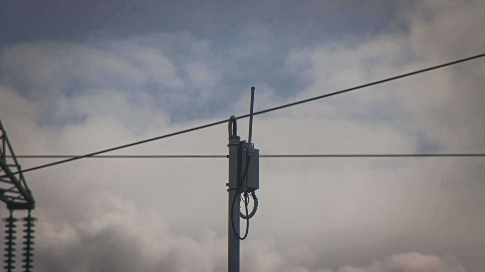
Featured image: Fabian Horst/Wikimedia Commons (CC BY-SA 4.0; cropped to 16:9).
RSSI is the received power level in dBm. It is negative in normal receiver reports, and a value closer to zero is stronger. SNR is the separation between that signal and the noise floor: SNR(dB) = received signal(dBm) − noise floor(dBm). LoRa can decode below the noise floor, so a negative SNR is not automatically a failed link.
Log a location matrix before changing hardware
Use one node, one payload interval and one radio configuration. Collect at least 20 uplinks at each gateway position under comparable conditions. Record median RSSI, median SNR, spreading factor, gateways heard and delivered packets. Repeat at the problem location and at a known-good control point.
A single packet can be misleading because people, doors, vehicles and nearby transmitters change the path. A median reduces the effect of one unusually good or bad frame, while the delivery count preserves the failures that a median cannot show.
Interpret RSSI and SNR as a pair
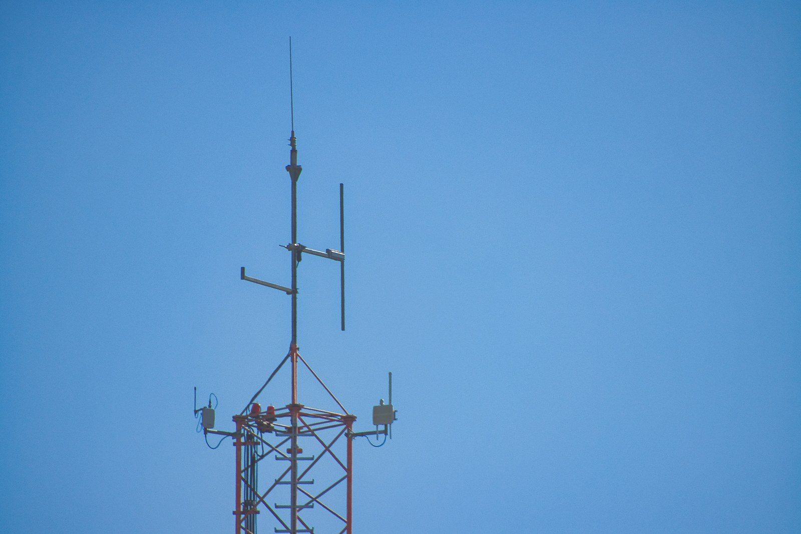
Weak RSSI with acceptable SNR points toward path loss: distance, walls, low antenna height, cable loss or poor polarization. Raising the gateway above local obstructions, moving it away from metal and shortening lossy coax are sensible first changes.
Relatively strong RSSI with poor SNR suggests that the receiver is collecting plenty of energy, but much of it is noise or interference. Moving the gateway a short distance from digital electronics, switch-mode supplies, USB 3 equipment or another transmitter can improve SNR without a dramatic RSSI change. A stronger antenna does not selectively amplify only the wanted packet.
Spreading factor reveals the airtime cost
The Things Network documents six LoRa spreading factors from SF7 through SF12. For each step upward, the chirp rate and data rate are halved. At 125 kHz and coding rate 1, its table lists about 5.5 kbit/s for SF7. The same page lists approximate 125-kHz receiver sensitivity from −123 dBm at SF7 to −137 dBm at SF12.
That sensitivity gain is not free. A fixed payload takes longer to transmit at a higher spreading factor, keeping the radio active longer and consuming more shared airtime. If a location only works by remaining at SF12, the link may deliver packets but still have little fade margin and impose a capacity penalty.
Change one physical variable at a time
Start with height and clearance because they do not add RF connectors. Then test lateral position, antenna orientation and separation from noise sources. If using external coax, include its specified loss and every adapter in the path. A rooftop antenna followed by a long, lossy cable can surrender much of the elevation benefit.
Keep antenna type and regional frequency plan correct. The Things Network notes that collinear gateway antennas are normally mounted vertically and commonly use Type N termination. Do not substitute an antenna intended for another band merely because its connector fits.
Use a before-and-after acceptance rule
Accept a placement change only if it improves delivery across repeated samples, not just the best RSSI. A useful record includes firmware version, frequency plan, data rate or spreading factor, transmit power setting, payload size, gateway location and timestamp. If Adaptive Data Rate is active, allow the network time to converge or hold the test configuration constant.
Semtech’s March 2024 AN1200.86 cites technology-level ranges up to 5 km in urban environments and 15 km or more in rural line of sight. Those are not placement promises. Buildings, terrain, antenna systems, regional limits and interference define the real link. Your measured matrix is the decision evidence.