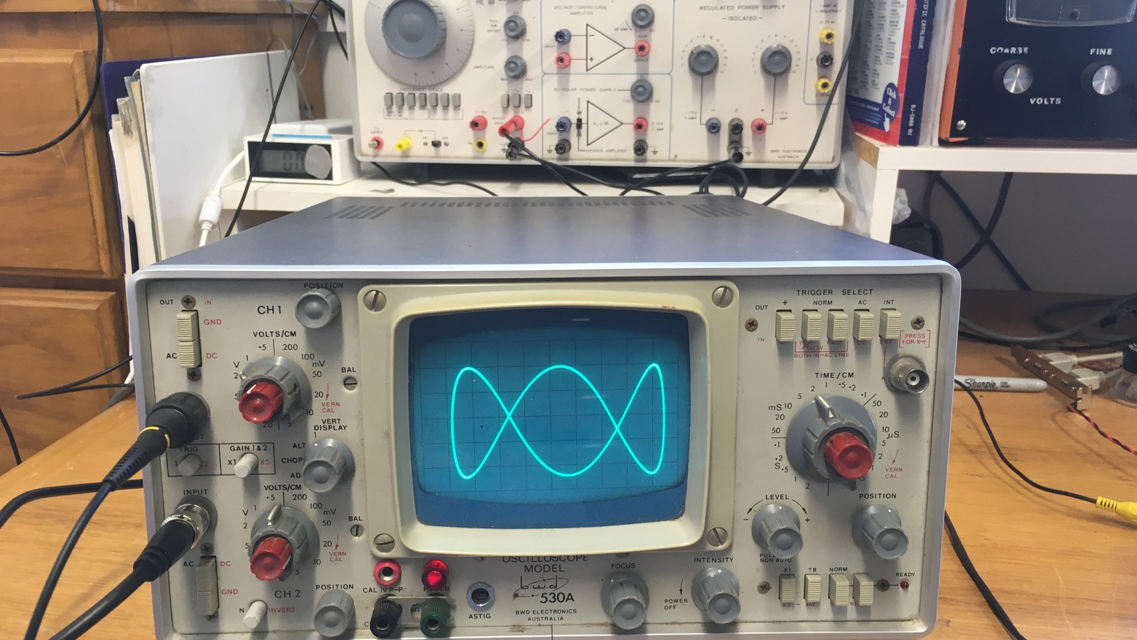
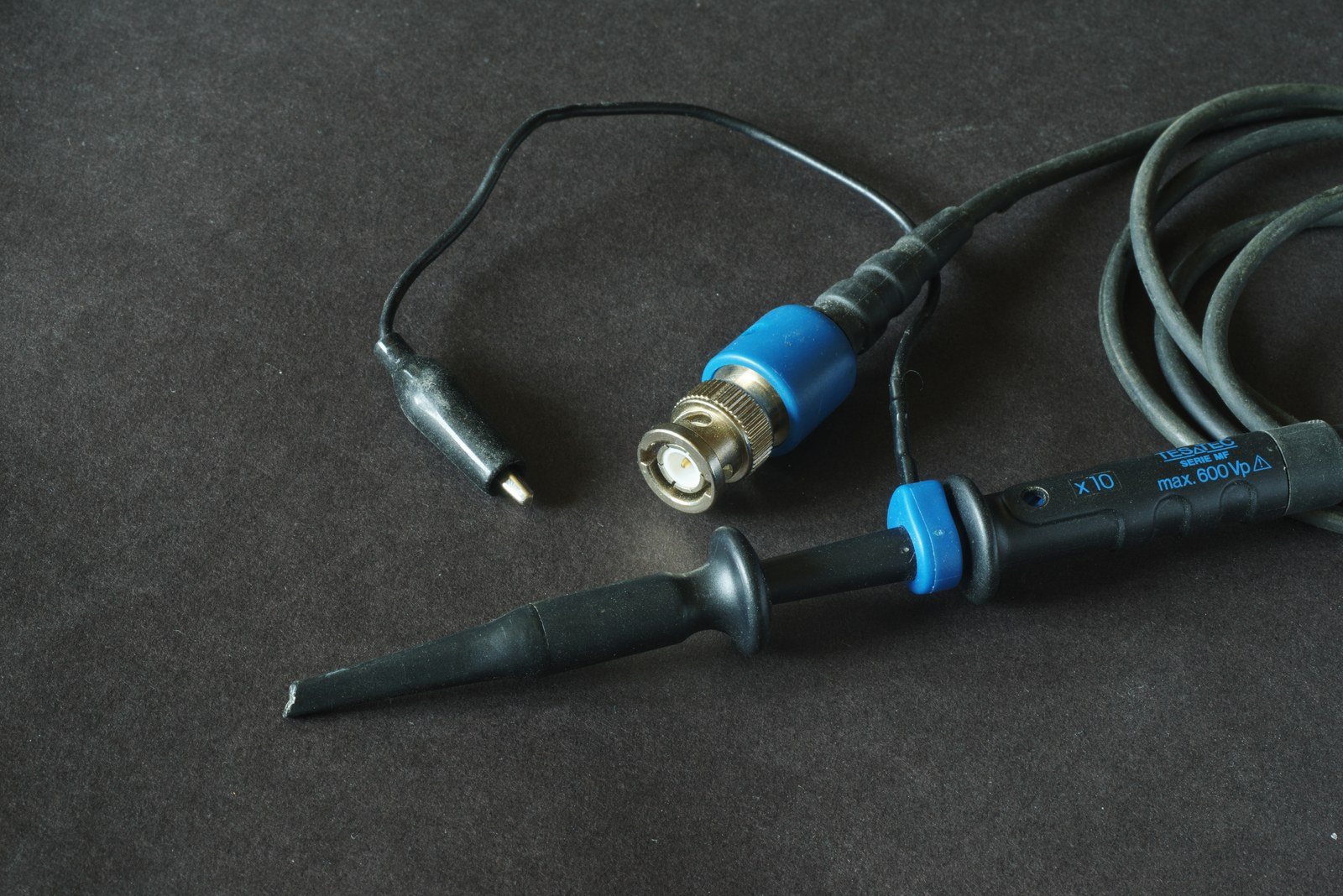
On most mains-powered bench oscilloscopes, the probe’s ground clip is not a floating zero-volt reference. It is bonded through the BNC shell and oscilloscope chassis to protective earth. Attach that clip to the wrong node and the probe can create a short before the tip measures anything.
Featured image: Peter Seligman/Wikimedia Commons (CC BY-SA 4.0; cropped to 16:9).
This is why a grounded scope behaves differently from a handheld battery multimeter. Tektronix describes the traditional oscilloscope “signal common” as connected to chassis and the third-wire protective ground. Pico Technology likewise warns that a grounded single-ended probe can put a low-impedance earth path onto the device under test.

Trace the connection before attaching the clip
For a low-voltage board powered by an isolated bench supply, attaching the clip to the board’s designated 0 V rail is often appropriate. The rail becomes earth-referenced through the scope. Trouble starts when the chosen point is not intended to be at earth potential: the switching node of a converter, the low side of a current shunt above ground, a rectified mains rail or one conductor of a non-isolated supply.
The fault path is physical: circuit node → probe ground lead → BNC shell → oscilloscope chassis → protective-earth conductor. Current is limited by wiring, source impedance and protection, not by the oscilloscope’s vertical scale. Sparks, damaged traces, tripped protection and electric shock are possible consequences.
Never solve this by lifting protective earth
Removing the earth pin, using a cheater adapter or feeding the oscilloscope through an isolation transformer can make exposed chassis and connector metal rise to the measured node’s voltage. Tektronix’s technical brief calls defeating protective grounding an unsafe and dangerous practice that should never be done. It can also stress insulation and leave a hazard after the instrument returns to ordinary service.
Channel subtraction is not input isolation
Two matched single-ended probes can measure two points relative to the same safe ground and the oscilloscope can display channel A minus channel B. This pseudo-differential method is useful for some low-voltage circuits. Both ground clips must remain at the same safe reference because the channel commons are connected inside the scope.
The method also combines channel and probe errors, loses a channel and may reject common-mode signal poorly when gains, delays or probes do not match. It does not authorize attaching either ground clip to a floating switching node.
Use a rated differential path for a floating node
A true differential probe measures between two inputs while rejecting voltage common to both. Selection requires more than bandwidth: verify maximum differential voltage, common-mode voltage versus frequency, measurement category, transient rating and the accessories fitted to the probe. Stay within the lowest rating anywhere in the measurement chain.
An oscilloscope with genuinely isolated inputs can be another solution, but “battery powered” does not automatically mean every channel floats independently or is safe at hazardous voltage. Tektronix’s cited battery-operated example applies explicit limits and grounding requirements above 30 V RMS or 42 V peak. Read the exact instrument and probe manuals.
A safe connection sequence
- Identify whether the circuit is isolated from mains and where protective earth already enters it.
- With power removed, check continuity from the intended reference to earth when that test is appropriate for the equipment.
- Compare expected differential and common-mode voltage, including transients, with probe and scope ratings.
- Connect the reference path before energizing only when the equipment manual calls for it; keep hands clear of exposed conductors.
- For mains, high-energy storage, motor drives or unfamiliar power electronics, use rated equipment and trained supervision rather than improvising.
The key question comes before bandwidth or sample rate: where will current flow when the ground clip touches this node? If the answer includes an unintended path to protective earth, stop and change the measurement method.