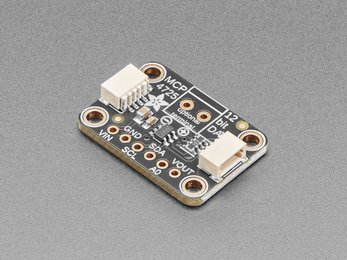
The MCP4725 does not generate an absolute voltage from code alone. Its 12-bit resistor-string DAC uses the chip’s supply, VDD, as the reference. Calculate the code from the measured supply, then decide whether that value should disappear at power-off or be stored in the device’s EEPROM.
Convert the target voltage to a 12-bit code
The ideal relationship is VOUT = VDD × code ÷ 4096. Solving for code gives code = round(4096 × Vtarget ÷ VDD), limited to the integer range 0 through 4095.
With VDD measured at 3.30 V, one least-significant bit is 3.30 ÷ 4096, or about 0.806 mV. A 2.00 V target gives round(4096 × 2.00 ÷ 3.30) = 2482. Substituting that value back into the transfer function produces an ideal 1.9997 V.
The same code does not represent the same voltage when VDD changes. Code 2482 at 5.00 V is about 3.030 V. Microchip’s data sheet explicitly notes that supply variation or noise directly affects DAC output, so a clean rail and a measured reference matter more than extra decimal places in software.
Resolution is not the same as accuracy
Twelve bits provide 4096 nominal steps, but step size only describes quantization. Offset error, gain error, integral nonlinearity, load and supply error move the real output away from the ideal equation. Microchip specifies operation from 2.7 V to 5.5 V and characterizes the output with a 5 kΩ load and 100 pF capacitance unless otherwise stated.
The data sheet lists 6 µs typical settling to within 0.5 LSB when the code changes from 0x400 to 0xC00 under its stated conditions. That figure does not mean arbitrary external loads settle in 6 µs. Wiring capacitance, buffering and the circuit connected to VOUT can extend the final response.
Use the DAC register for motion and EEPROM for startup
The volatile DAC register changes the live output. The EEPROM holds a power-up value and power-down configuration; after reset, the device copies those fields back into the DAC register. Adafruit’s guide summarizes the practical result: a stored voltage can return after a power cycle.
That does not make EEPROM the right destination for every sample in a waveform or control loop. Use volatile writes for ordinary output changes. Reserve an EEPROM write for a configuration that genuinely needs to survive power loss, such as a safe bias or startup setpoint. This also avoids making a slower nonvolatile operation part of the real-time update path.
Check addressing and the load before blaming the code
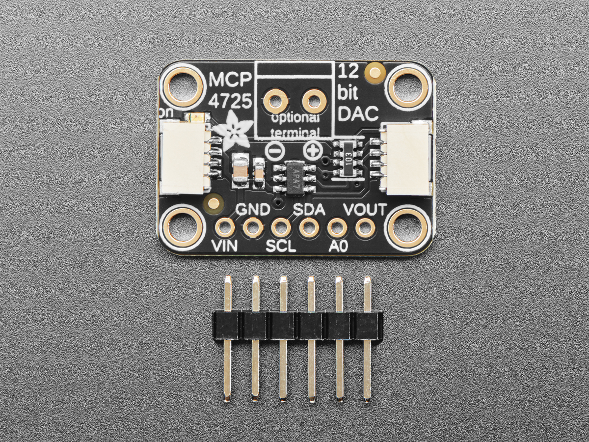
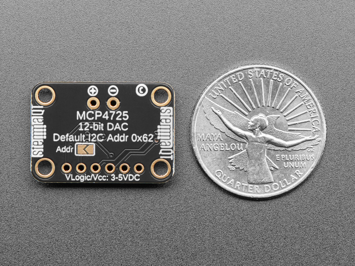
The breakout exposes A0 so two address variants can share one I²C bus; Adafruit notes that one board can pull the address pin high or close its rear jumper to avoid a conflict. If writes are acknowledged but VOUT is wrong, measure VDD at the board, read back the commanded code where the library allows, and disconnect or buffer a heavy load.
A DAC is not a power supply. The output amplifier is intended to create a control or bias voltage, not directly drive a motor, heater or low-impedance speaker. For those loads, use the DAC as the command source for an appropriate buffer or driver stage.
If the real problem is input conversion rather than output generation, the arithmetic runs in the opposite direction. TVG’s MCP3008 reference-voltage guide covers converting ADC codes into measured voltage.