A 10 kΩ NTC thermistor does not produce temperature directly. It produces a resistance that changes nonlinearly, so a microcontroller must first measure a divider voltage, convert that ADC code back to resistance and then apply the thermistor’s beta value or a manufacturer resistance table. Reversing either divider assumption produces readings that move in the wrong direction or miss by tens of degrees.
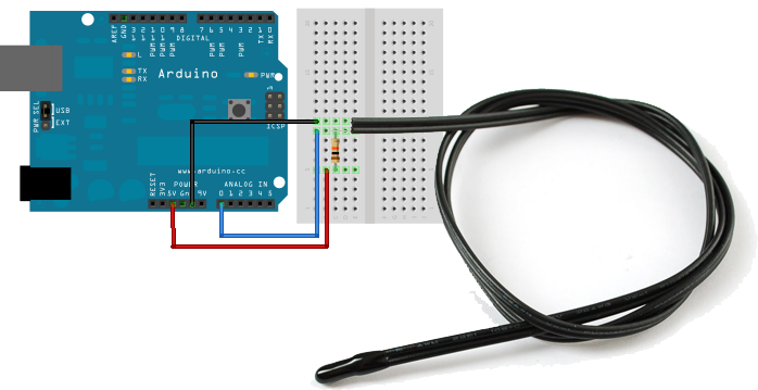
Featured image: Adafruit.
Start with the divider orientation
In the Adafruit circuit, a fixed 10 kΩ resistor runs from the supply to the ADC node, and the NTC thermistor runs from that node to ground. With that orientation, the measured voltage is:
Vout = Vcc × Rntc / (Rfixed + Rntc)
An NTC’s resistance falls as it warms, so Vout and the ADC code also fall. If a project warms the probe and sees the code rise, either the fixed resistor and thermistor are swapped or the conversion equation assumes the opposite orientation.
Convert ADC code to resistance before temperature
For a 10-bit ADC whose full-scale code is 1023, solve the divider equation for the thermistor resistance:
Rntc = Rfixed / (1023 / ADC - 1)
The equivalent form is Rntc = Rfixed × ADC / (1023 - ADC). The result is valid for the stated wiring orientation. A 512 code with a 10 kΩ fixed resistor gives about 10.02 kΩ, which is close to the nominal resistance of a 10 kΩ thermistor at 25 °C.
Do not hard-code 1023 for every platform. An ADC returning 12-bit codes has a full-scale code of 4095. In general, replace 1023 with 2^N - 1, where N is ADC resolution. Also guard the calculation against zero and full-scale readings; those endpoints make the equation divide by zero and usually indicate an open, shorted or saturated input.
Use the beta equation with kelvin
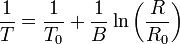
For Adafruit’s product 372, the nominal values are 10 kΩ at 25 °C and B25/50 = 3950 K, each with a stated ±1% tolerance. The simplified beta equation is:
1/T = 1/T0 + ln(R/R0)/B
Here T and T0 are in kelvin, R0 is 10,000 Ω at T0 = 298.15 K, and B is 3950 K. After solving for T, subtract 273.15 to report degrees Celsius. Feeding 25 instead of 298.15 into the reciprocal term is a unit error, not a calibration issue.
Make the ADC measurement ratiometric
If the divider supply and ADC reference are the same electrical node, the supply voltage cancels from the code-to-resistance calculation. That is useful because a small supply change moves both the divider output and ADC full scale together. Using one rail for the divider and an unrelated reference breaks that cancellation and requires the actual voltages in the calculation.
Noise still matters. Adafruit’s guide recommends taking five samples and averaging them, and it shows a 10 ms delay between samples. Averaging can reduce random code jitter, but it cannot correct the wrong beta coefficient, resistor tolerance, self-heating or poor thermal contact.
Separate sensor limits from calculation limits
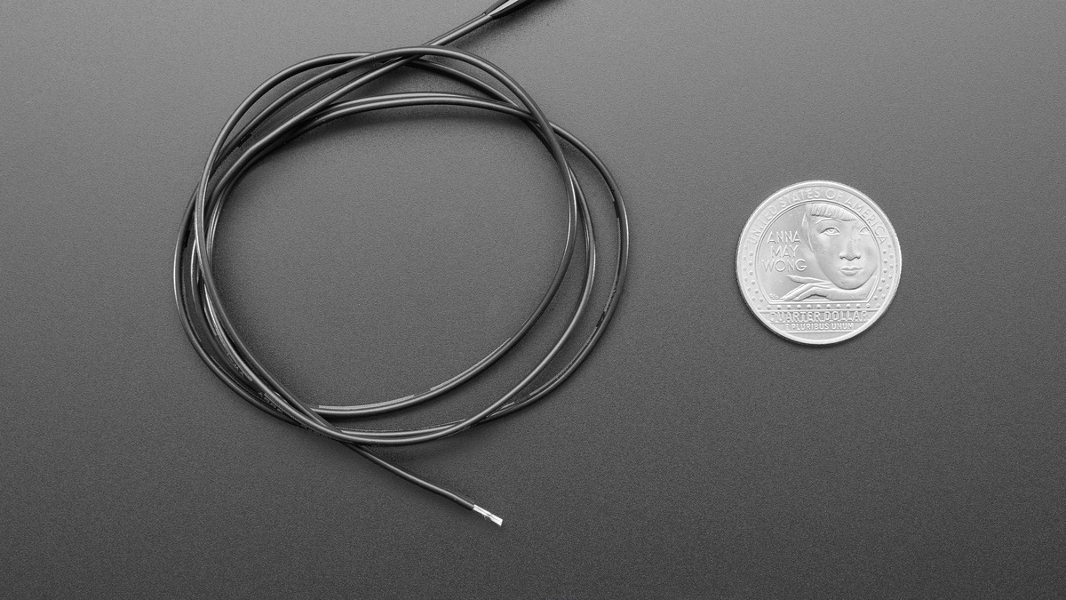
The product listing gives a thermistor range of −55 °C to 125 °C, a thermal time constant of no more than 15 seconds and PVC wire rated to 105 °C. That means the lead insulation can become the practical upper-temperature limit before the sensing element reaches its advertised maximum. The time constant also means a slowly changing reading may be normal; software smoothing should not be added until the probe’s physical response has been considered.
The beta equation is an approximation. For tighter accuracy across a wide range, use the manufacturer’s resistance-versus-temperature table or Steinhart–Hart coefficients for the exact part. A one-point correction at room temperature can remove a fixed offset, but it cannot fully correct curvature caused by the wrong beta value.
A quick fault map
- ADC near zero: inspect for a thermistor short, node short to ground or disconnected fixed resistor.
- ADC near full scale: inspect for an open thermistor, node short to the supply or disconnected ground path.
- Temperature moves backward: verify divider orientation and whether the code uses the matching resistance equation.
- Correct near 25 °C but wrong at the ends: verify the exact beta value or switch to the part’s lookup table.
- Stable offset everywhere: check the fixed-resistor tolerance, reference arrangement and probe placement before adding calibration.