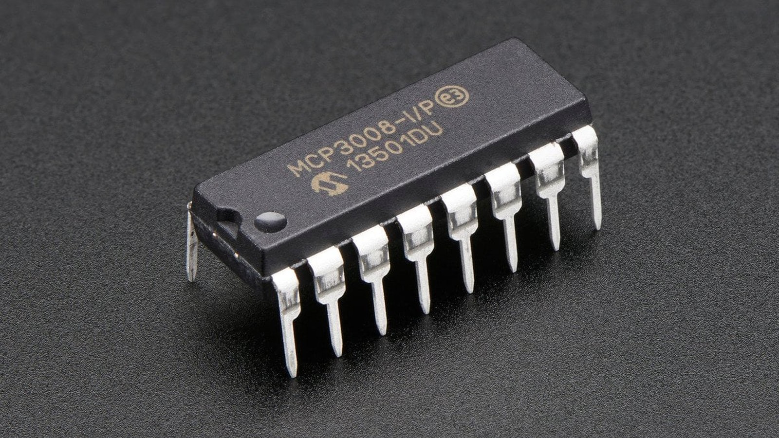
An MCP3008 conversion result is not a voltage until it is scaled by the converter’s reference. The correct ideal conversion is volts = code × VREF / 1024. Dividing by 1023 forces the highest code to equal VREF and changes the transfer function the datasheet defines.
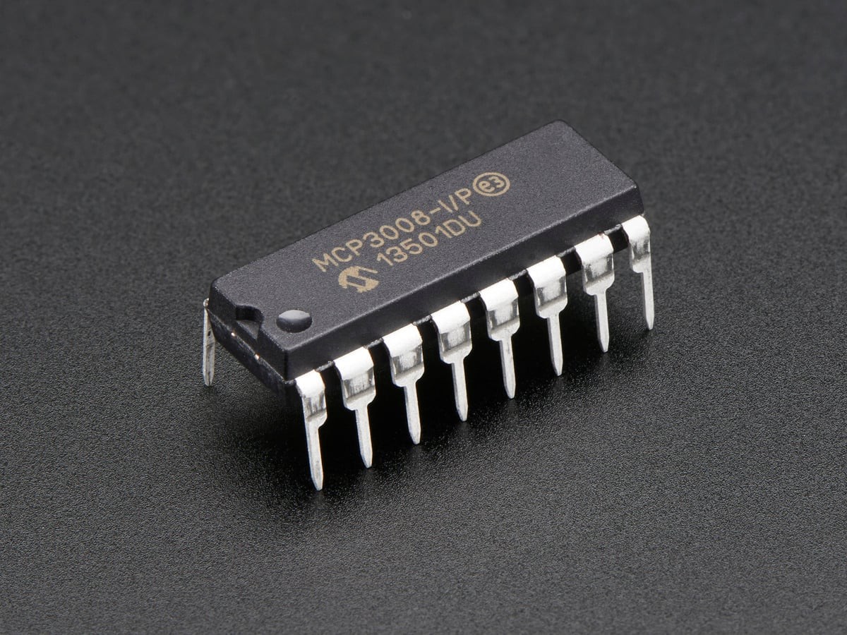
Featured image: Adafruit.
The Microchip MCP3008 datasheet describes a 10-bit successive-approximation converter with eight input channels and an SPI-compatible serial interface. Ten bits produce 1024 possible codes, numbered 0 through 1023.
Use 1024 intervals, not the highest code
The ideal LSB size is VREF / 1024. With a 3.3 V reference, one LSB is 0.00322265625 V. A reading of 512 therefore represents about 1.65 V, while code 1023 represents about 3.29678 V. With a 5.0 V reference, the corresponding values are 4.8828125 mV per LSB and about 4.99512 V at code 1023.
This distinction is small but systematic. Dividing by 1023 maps every nonzero code slightly high. More importantly, writing a literal 3.3 or 5.0 into software assumes the reference rail is exact. If VREF measures 3.267 V at the converter, that measured value belongs in the conversion.
Reference error moves every channel together
The MCP3008 reports an input as a ratio to VREF. If the reference changes by 1%, calculated voltages change by roughly 1% even when the raw code is stable. A sensor powered from the same rail can sometimes be read ratiometrically, but an independently referenced voltage still inherits reference uncertainty.
That creates a useful diagnostic split. A wrong raw code points toward input range, wiring, channel selection or acquisition. A consistent scale error across channels points toward the reference value or conversion arithmetic. A noisy code near a boundary may simply be quantization plus source noise.
Sampling speed does not guarantee input settling
Microchip specifies throughput up to 200 ksps at 5 V and 75 ksps at 2.7 V. Those are converter limits under stated conditions, not promises that any sensor can drive the input accurately at those rates. The internal sample-and-hold capacitor must charge through the signal source during acquisition.
A high-impedance divider, large series resistor or multiplexed sensor network can leave the sample capacitor short of the input voltage. Slowing the SPI clock, allowing acquisition time, lowering source impedance or adding a buffer can improve settling. That failure mechanism is different from choosing the wrong VREF.
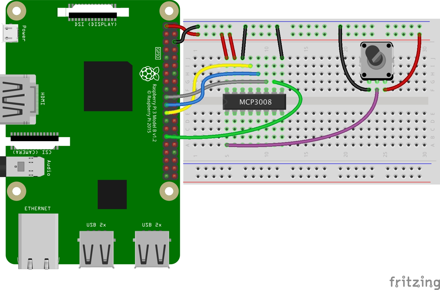
The Adafruit integration guide provides practical wiring context. For systems already using a higher-resolution converter, TVG’s ADS1115 clipping guide explains a separate failure: full-scale gain selection can saturate a 16-bit result even when the sensor itself is healthy.
Keep the raw code beside the engineering value
Log the raw 0–1023 code, the VREF value used and the converted voltage. That three-part record preserves enough evidence to distinguish a math change from a rail change later. Converting immediately to a rounded voltage and discarding the code removes that diagnostic path.