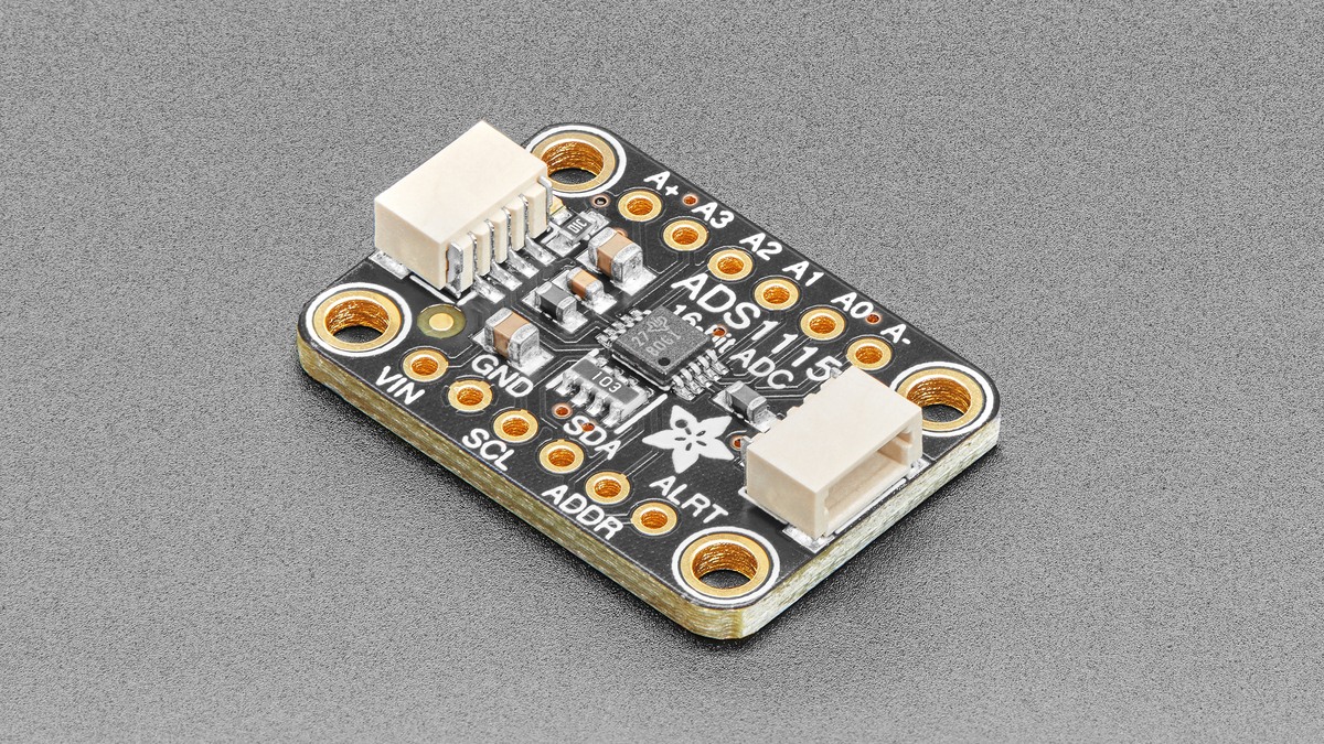
An ADS1115 that repeatedly returns 0x7FFF is usually not gaining precision; it has reached the largest positive code in its signed 16-bit conversion register. The useful checks are the selected programmable-gain range, the actual input voltage and the channel configuration—not more averaging.
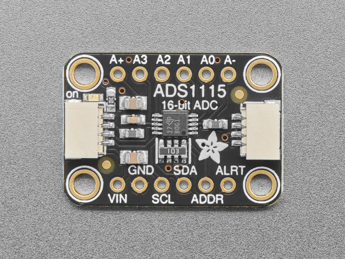
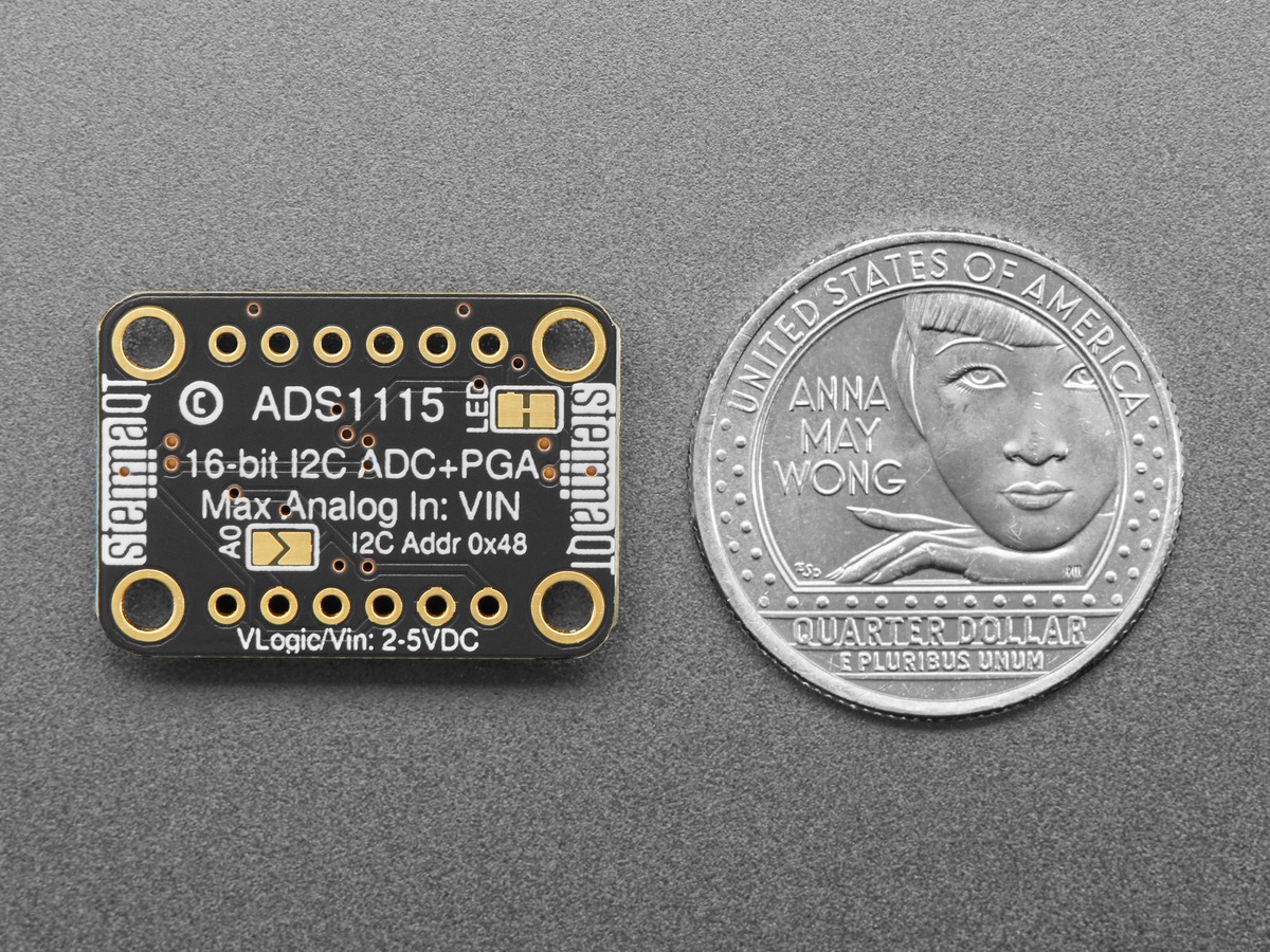
Featured image: Adafruit.
Texas Instruments defines ADS1115 output as two’s-complement data. Positive full scale is 0x7FFF, while negative full scale is 0x8000. A value parked at either endpoint means the converter can no longer represent changes in that direction under the current configuration.
Match the PGA range to the signal before changing software scale
The programmable gain amplifier offers full-scale ranges of ±6.144, ±4.096, ±2.048, ±1.024, ±0.512 and ±0.256 V. A smaller range gives a smaller volts-per-code value, but it also clips at a lower differential input. Selecting ±0.256 V for a signal that reaches 0.4 V does not reveal finer detail above 0.256 V; it converts every higher value to the same endpoint code.
Read the configuration register or the exact gain constant passed to the driver. Then convert several raw signed samples to volts using the scale for that range. If raw values stay at 32767 while the source continues rising, move to a wider range or attenuate the input within the device’s electrical limits.
Full-scale range is not the same as safe pin voltage
The ±6.144 V setting describes the converter’s differential measurement scale. It does not authorize an input pin to exceed the supply rails. The TI datasheet constrains analog inputs relative to GND and VDD, so a board powered at 3.3 V cannot safely accept 6 V merely because the PGA has a ±6.144 V option.
That distinction matters in resistor-divider and battery measurements. Calculate the pin voltage at the highest possible source value, including tolerance and transient margin. Choose the divider for pin safety first; then choose the narrowest PGA range that contains the resulting differential signal.
Single-ended mode uses only the positive half
In single-ended mode the ADS1115 measures A0, A1, A2 or A3 against ground. Negative source voltages are outside the intended single-ended measurement path, and the useful code span is 0 through 32767. Differential mode can represent both polarities because it measures one analog input against another.
Confirm that the multiplexer selection matches the wiring. Reading A0-to-GND while the signal is wired between A0 and A1 changes both the reference and the expected sign. Adafruit’s gain examples pair each gain constant with a volts-per-bit scale, while the library source shows how those settings enter the configuration word.
Averaging cannot restore clipped amplitude
The ADS1115 supports data rates up to 860 samples per second. Faster sampling or a longer average can reduce random variation within range, but a series of identical 0x7FFF results contains no information about how far the original signal exceeded full scale. First remove clipping; only then evaluate noise and averaging.
A compact diagnostic record should include the raw signed code, selected PGA range, VDD, multiplexer setting and a separately measured input voltage. Those five values distinguish conversion saturation from unsafe overvoltage, wrong-channel wiring and software that mistakenly treats a signed result as unsigned. For another signed measurement path, TVG’s INA219 current-direction guide explains why register sign and physical polarity must agree.