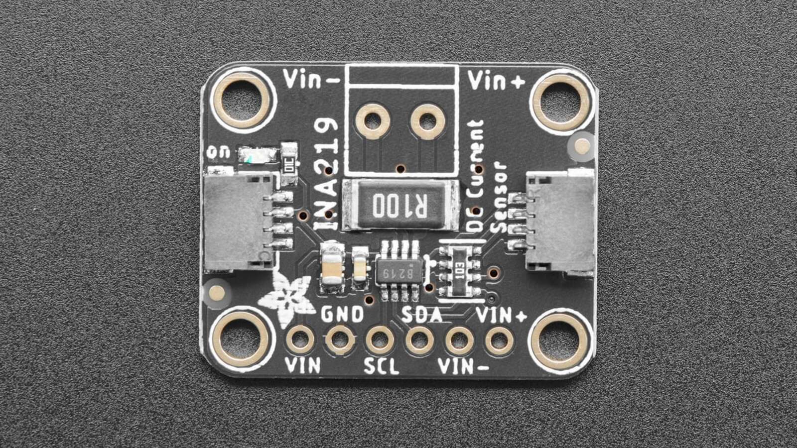
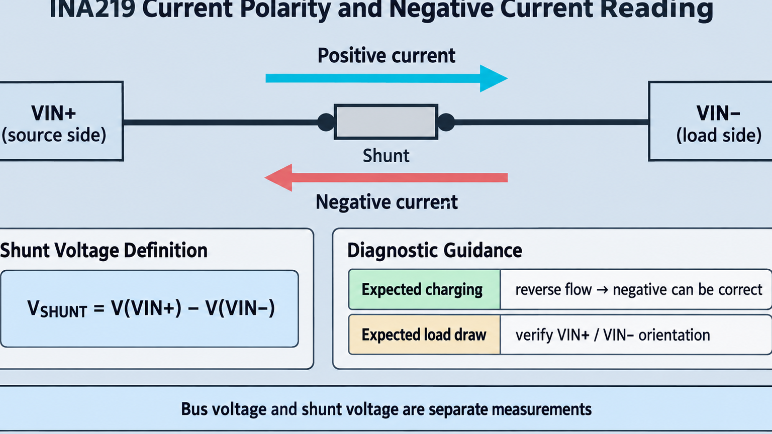
A negative INA219 current reading is not automatically a calibration failure. The device measures the differential voltage from VIN+ to VIN−; current flowing from the marked source side toward the load side is positive, while real reverse flow—or swapped source and load connections—produces a negative result.
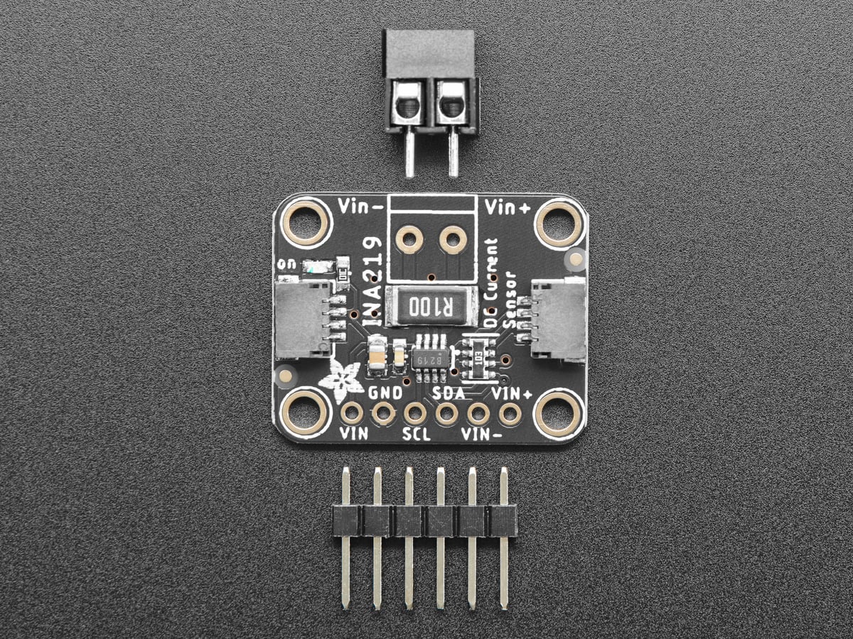
Featured image: Adafruit.
Start with shunt voltage rather than rewriting calibration constants. Texas Instruments defines the measurement as the voltage at VIN+ minus the voltage at VIN−. A negative shunt voltage proves that the differential polarity is reversed at that moment; the remaining question is whether that reversal is expected.
Decide whether reverse flow is physically valid
Adafruit labels VIN+ as the source side and VIN− as the load side for a conventional high-side measurement. A battery-powered load normally draws current from source to load and should produce a positive sign. If the board is installed backward in that path, both shunt voltage and calculated current can be negative even though the load operates normally.
Bidirectional systems are different. A rechargeable battery, motor regenerative path or shared supply can legitimately push current from the nominal load side toward the source. In that state, a negative reading contains useful direction information. Confirm the operating mode before swapping terminals merely to make the number positive.
Compare shunt voltage and current signs
The INA219 reports bus voltage and shunt voltage separately. Bus voltage is measured at VIN− relative to ground; shunt voltage is the small differential across the current-sense resistor. A plausible positive bus voltage can coexist with a negative shunt voltage, so the bus reading alone cannot establish current direction.
Read both values in one diagnostic log. If shunt voltage and current are both negative, the sign is internally consistent: inspect physical direction and VIN+/VIN− orientation. If shunt voltage is negative but the application prints a huge positive current, inspect the driver’s signed conversion and data type. The shunt and current registers represent signed quantities; treating a two’s-complement value as unsigned changes its meaning.
The INA219 supports programmable shunt full-scale ranges up to ±320 mV. Exceeding the selected range is not fixed by changing display units. Verify the actual differential voltage and the shunt value before using the reading for protection or energy accounting.
Calibration affects scale, not physical polarity
The INA219’s Current register is derived from the measured shunt voltage and the programmed Calibration register. Texas Instruments defines a chosen Current_LSB and a calibration value based on that scale and the shunt resistance. A zero Calibration register disables meaningful Current and Power register calculations; a wrong value produces the wrong magnitude.
Calibration is therefore the next branch only after polarity is understood. Confirm that the library initialization routine ran after power-up or reset, then compare its assumed shunt resistance with the actual board. Adafruit’s breakout uses a marked current-sense resistor and its library presets choose a corresponding range. A clone with a different shunt value needs matching calibration rather than copied constants.
For a quick consistency check, use I ≈ VSHUNT / RSHUNT with volts and ohms. The result should have the same sign as the reported current. This calculation is a diagnostic cross-check, not a substitute for respecting the device’s input range, resistor power rating and wiring limits.
Use one polarity convention throughout the project
After verifying the hardware, document what positive current means: load draw, battery discharge, charging current or another system-specific direction. Do not hide a reversed installation by multiplying every result by −1 unless that convention is explicit and stable. Alarms, accumulated energy and state-of-charge calculations all depend on the same sign definition.
If the application still shows an impossible sign, capture raw shunt voltage, current-register value, Calibration register state and operating mode in the same sample. That record separates a real current reversal from a wiring mistake or software conversion fault. TVG’s current-loop open-circuit fault isolation covers a different current-measurement topology and should not be used as an INA219 wiring reference.