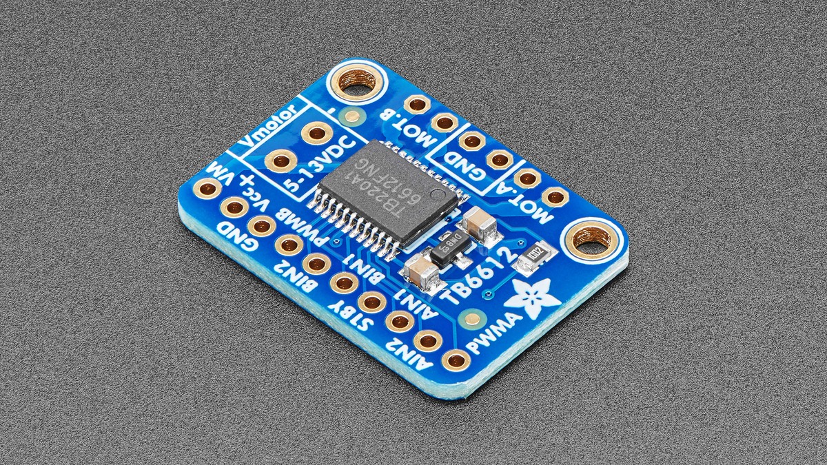
A TB6612FNG channel can remain completely still even when the motor and driver are healthy. The chip will not drive either output if global STBY is low, and each channel also needs active PWM plus an IN1/IN2 combination that selects a direction rather than stop or brake.
Featured image: Adafruit.
Diagnose those controls as separate layers. A single measurement or code inspection at the motor terminals can otherwise confuse an intentional truth-table state with a damaged bridge, missing supply or stalled load.
Prove both power domains before reading control pins
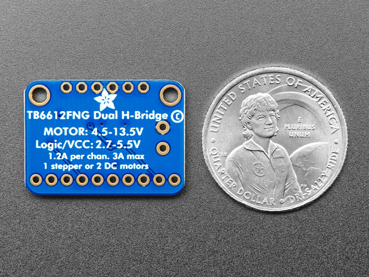
The Toshiba part has a logic supply, VCC, specified from 2.7 to 5.5 V, and a motor supply, VM, specified from 2.5 to 13.5 V. The grounds must share a valid reference. A microcontroller can toggle logic correctly while an absent VM leaves the motor outputs without energy.
Measure VCC-to-GND and VM-to-GND at the breakout, not only at the bench supply. Then confirm the motor supply remains present when a drive command begins. A collapsing VM points to the supply, wiring, connector or load current rather than the truth table.
STBY is a global gate
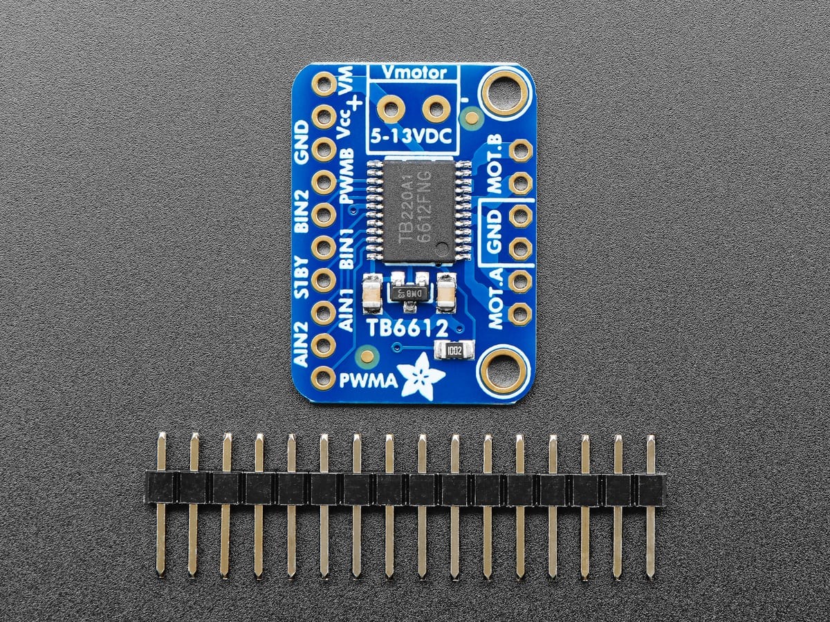
STBY low places both H bridges in standby. Adafruit’s breakout pulls that pin up to VCC through 10 kΩ, so it can run without a dedicated standby signal in a simple build. A jumper to ground, a microcontroller pin still configured as output-low or a poor logic supply can override the intended high state.
Measure STBY while the software believes the driver is enabled. If both motor channels fail together, this global gate and the shared power rails deserve attention before per-channel direction code.
PWM and IN1/IN2 answer different questions
The PWM input controls whether a channel switches; the two direction inputs select the bridge state. For channel A, AIN1=HIGH and AIN2=LOW selects one direction, while the opposite pair selects reverse. Equal inputs do not request motion: both high selects short brake, and both low selects the high-impedance stop state documented by Toshiba.
Temporarily command a simple state with PWM continuously high and one unequal input pair. Verify those levels at PWMA, AIN1 and AIN2. If that works, reintroduce PWM and direction changes one at a time. This separates a pin-mapping or duty-cycle problem from the bridge and motor.
Interpret output voltage in the commanded state
With standby released, PWM high and unequal direction inputs, the two motor outputs should have opposite drive states. Measure across AO1 and AO2, because measuring one terminal to ground can be misleading in an H bridge. Reversing the input pair should reverse the differential polarity.
If the command pins and unloaded differential output are correct but the motor does not turn, disconnect power and check the motor and leads. If the unloaded output is absent despite valid power and logic, inspect solder joints and output shorts. A bridge that moves briefly and then stops under load belongs on a thermal or overcurrent branch; TVG’s motor-driver heat guide covers that separate failure path.
The shortest reliable sequence is therefore power domains, global standby, PWM, direction truth table, unloaded differential output and finally the mechanical load. Each step changes one boundary and produces evidence about the next.