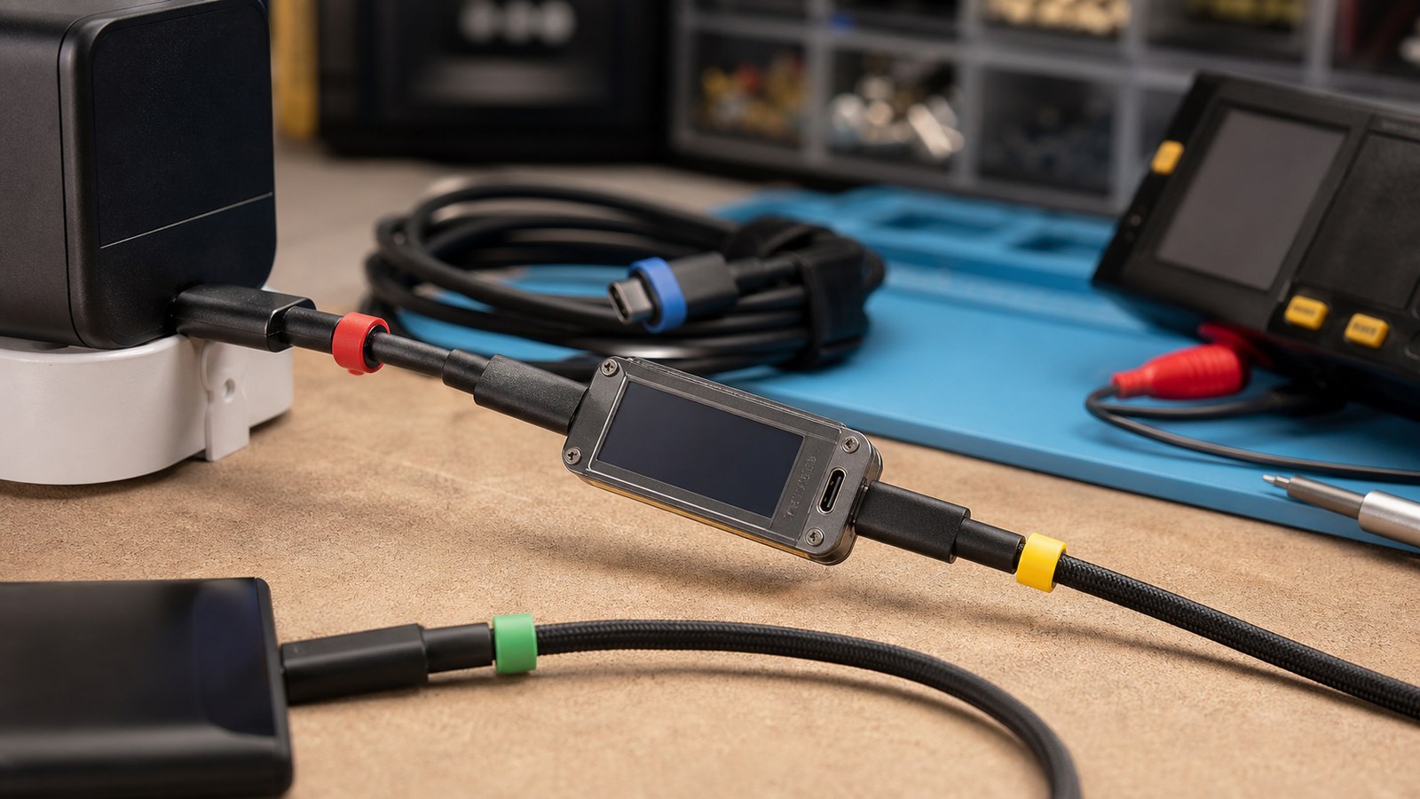
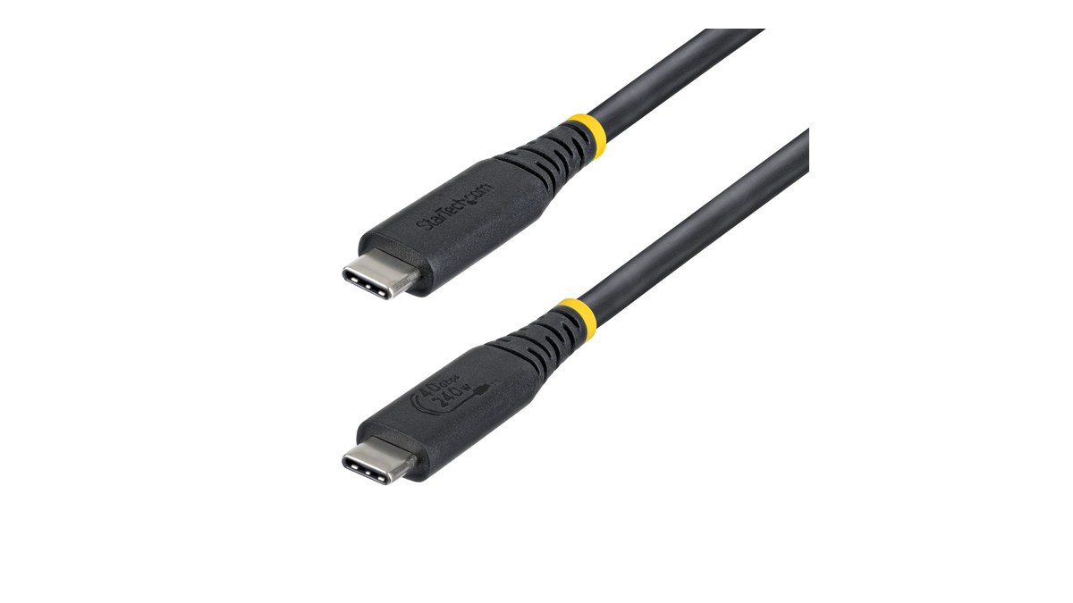
USB-C PD cable markers are the hidden detail that tells chargers, docks, and devices what a cable can safely carry. Maker labs should check the marker before trusting the wattage label.
That is the mistake cable markers are meant to prevent. In the USB-C ecosystem, electronically marked cables can advertise cable capabilities so the source, sink, and cable are not treated as interchangeable pieces of wire. For maker labs, the practical lesson is simple: do not debug a high-power USB-C project until the cable is identified, labeled, and tested under the expected load.
Quick answer
For USB-C PD projects above basic low-power use, check the charger, PD trigger, cable rating, connector quality, load current, voltage request, and thermal behavior as one system. A 100 W or 240 W label on one component does not make the whole project safe.
Why cable markers matter
USB Power Delivery lets devices negotiate voltage and current instead of assuming a fixed 5 V supply. That flexibility is useful for robots, portable monitors, battery chargers, field lights, micro PCs, and test benches. It also creates a failure mode that older barrel-jack projects rarely had: the cable can quietly become the weakest part of the power path.
The USB Implementers Forum publishes the USB Type-C cable and connector specification and USB Power Delivery specification as the canonical references. Those documents are written for implementers, but maker labs can still translate them into a workflow: treat every cable as a rated component, not an accessory.
A practical bench checklist
- Identify the voltage request. Know whether the project asks for 5 V, 9 V, 12 V, 15 V, 20 V, or extended power-range behavior.
- Confirm the cable rating. Do not assume a cable supports the current or voltage implied by the charger.
- Measure at the load. Voltage at the adapter is less useful than voltage at the board while motors, lights, radios, or displays are active.
- Watch temperature. A connector that becomes warm during a short test deserves investigation before enclosure installation.
- Keep a known-good cable set. Mark them for lab use and keep unknown giveaway cables out of power testing.
This also connects directly to TVG’s recent guide, USB-C Cable Tester or Multimeter? Maker Field Kits Need Both. A tester can identify many cable and wiring problems quickly, while a multimeter or power meter confirms the behavior under load.
How to document a known-good power path
TVG recommends keeping a small project power record with the charger model, cable identifier, trigger-board setting, fuse or protection method, measured load current, and observed connector temperature after a realistic run. The document does not need to be formal. It needs to survive a classroom, competition pit, or field repair where someone else may grab a cable from the wrong bin.
For projects that move, add one more entry: how the cable is retained. A USB-C connector can be electrically correct and still unreliable if vibration slowly walks it out of the socket or if a tight bend transfers every bump into the connector shell.
Common failure patterns
The most common lab problem is substitution. A project is validated with one cable, packed for an event, then powered with another cable that looks similar but behaves differently. The second problem is mechanical: repeated plugging, strain, and enclosure pressure can damage a connector long before the board fails electrically.
For mobile robots and field rigs, cable routing matters as much as cable rating. A cable that is electrically correct but bent sharply against a moving joint or enclosure edge is still a reliability risk.

TVG Take
The best USB-C PD upgrade is not the biggest charger. It is a repeatable bring-up procedure: known cable, known trigger, known load, measured voltage, thermal check, and a label that survives the next demo day. Maker labs that treat cables as documented parts will spend less time chasing random resets and more time testing the actual project.