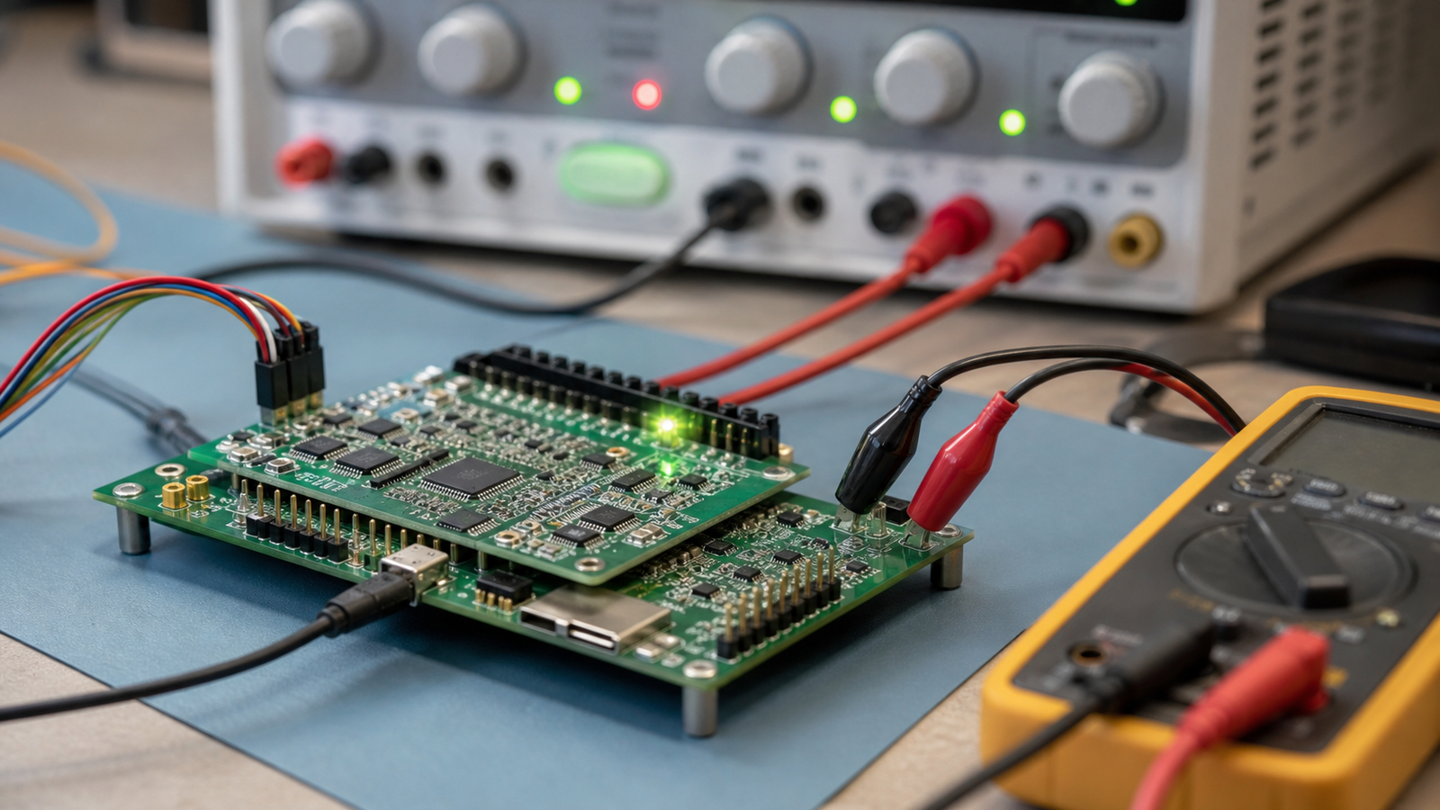
A bench power supply current limit is a safety feature, not just a setup knob. Set it before connecting a new board, motor driver, sensor rail, or student wiring harness.
Tektronix describes a bench power supply as a DC source for a device under test, with voltage, current, and power limits among the practical selection criteria. In a real workshop, those limits are not only spec-sheet numbers. They are part of the test method.
Quick answer
Set the bench supply voltage for the circuit, then set a conservative current limit before the first power-on. Start low, watch whether the supply enters current-limit behavior, and raise the limit only when the load behavior is understood. Do not use a high-current supply as if the circuit will magically take only what it should.
What the current limit does
A normal bench supply can operate as a constant-voltage source until the load tries to draw more current than the limit allows. At that point, it may reduce voltage to hold current near the limit. That behavior can reveal a short, reversed wiring, overloaded regulator, stalled motor, or wrong LED resistor before the full fault current flows.
The details vary by supply. Some instruments make constant-voltage and constant-current state obvious; others show it with a small indicator. The lab habit should be the same either way: set the limit intentionally, then observe whether the device behaves as expected.
This is the same thinking behind TVG’s USB-C PD trigger-board guide. A voltage source can look convenient while hiding a larger power-budget problem. A current limit forces the builder to make that budget visible.
First-power-on checklist
- Know the target voltage: do not guess between 3.3 V, 5 V, 9 V, and 12 V because the connector fits.
- Start with a low current limit: choose a value that is enough for standby current but below the likely damage level.
- Check polarity and ground: verify the power path with a meter before connecting a new board.
- Power subsystems separately: test logic, sensors, LEDs, and motors in stages when possible.
- Watch startup behavior: a short current spike may be normal; a supply that sits in current limit is a clue.
- Document the final setting: write down the voltage and current used for the next person.
Where makers get fooled
One common mistake is setting the voltage correctly and leaving the current limit at the supply’s maximum. That can turn a small wiring error into a board-level failure. Another mistake is interpreting current limit as a finished diagnosis. A current-limited supply tells you the load is demanding more current than allowed; it does not tell you exactly why.
Robot builders see this often. Motors, servos, radios, cameras, and sensors can create startup loads that look different from steady-state operation. TVG’s power-rail noise guide covers the next layer: after the board powers on safely, measure behavior under realistic loads.
What to buy for a small lab
For a school, makerspace, or home electronics bench, look for clear voltage and current controls, readable indicators, output enable, enough power for the intended loads, and terminals that accept safe leads. Multiple outputs can be useful, but only if the lab has rules for grounding and series/parallel use.
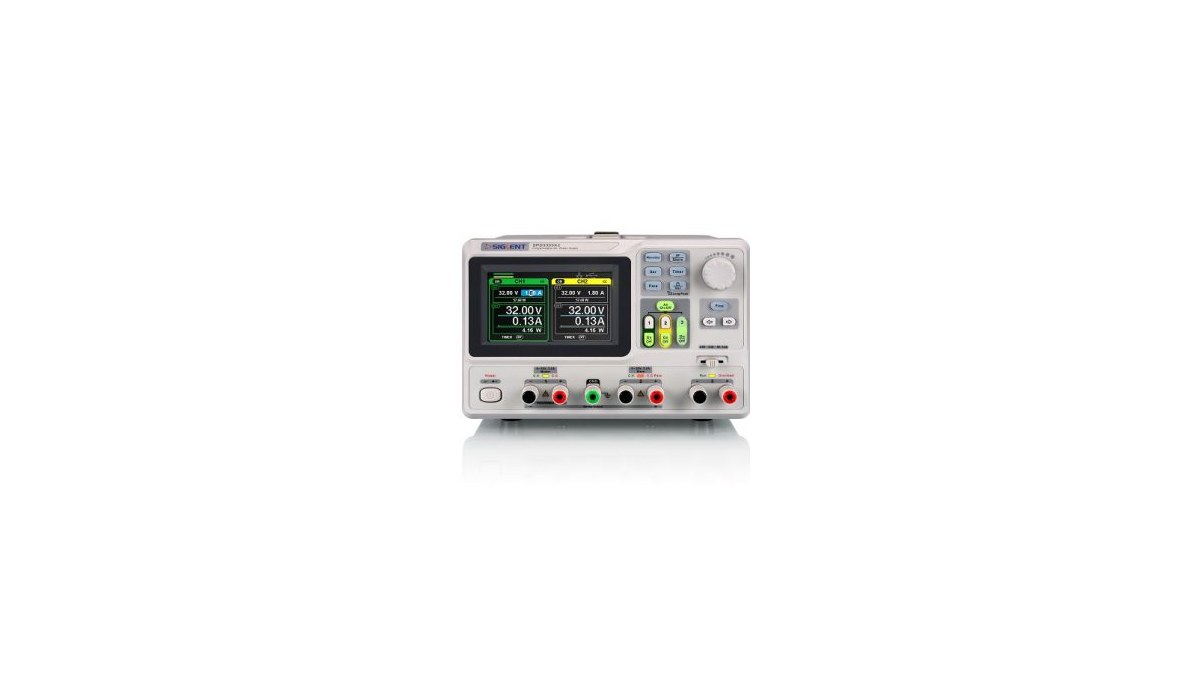
The best supply is not necessarily the largest one. A modest supply with a good current-limit workflow can be safer for students and prototypes than a powerful unit used carelessly.
TVG Take
Current limiting is not a premium feature for expert benches. It is a basic safety and debugging habit. If a maker lab teaches only “set the voltage and turn it on,” it is skipping the part that protects hardware and builds real engineering judgment.