Set an A4988 current limit from the carrier’s sense-resistor value, not from a copied VREF number. On Pololu carriers made since 2017, the 0.068 Ω resistors make a 1.00 A limit approximately 0.544 V; older 0.050 Ω boards need 0.400 V for the same limit.
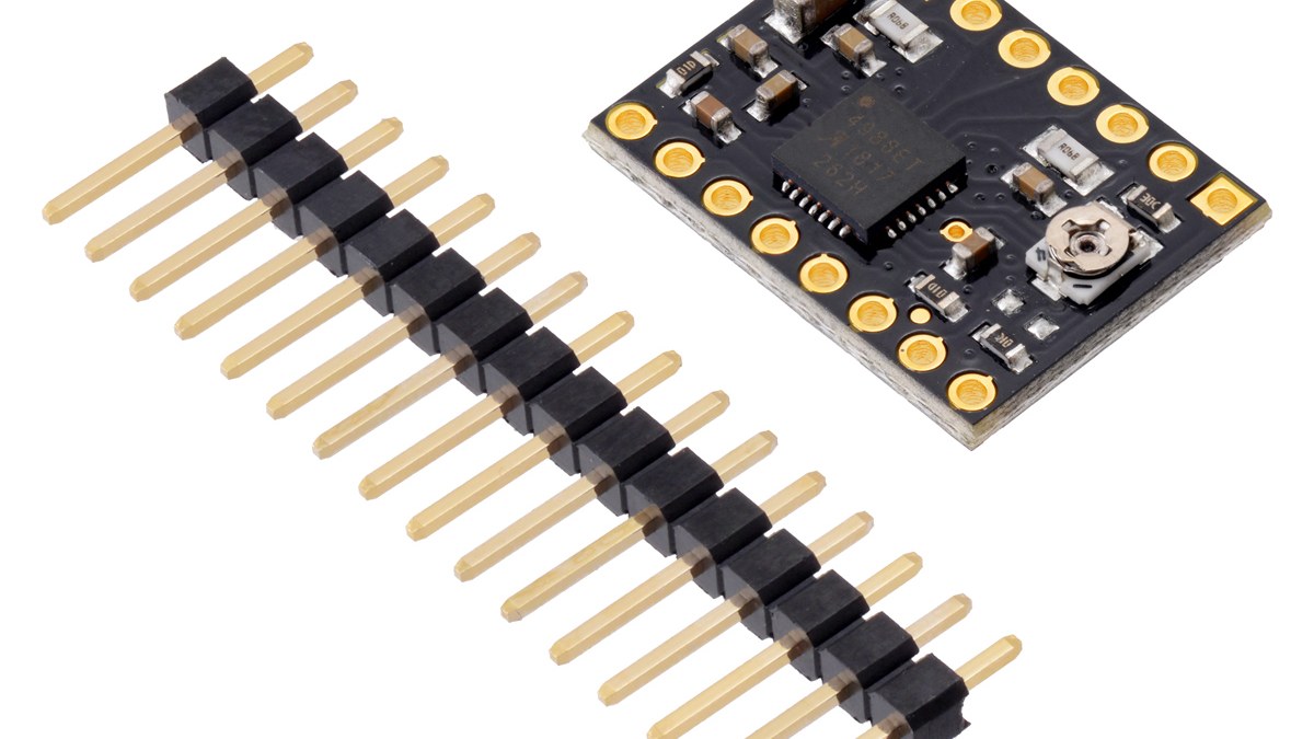
Featured image: Pololu.
The second common error is measuring one coil in full-step hold and treating that reading as the configured limit. Pololu documents that each coil carries about 70% of the set limit in this state.
Start with the trip-current equation
The A4988 relationship used by Pololu is:
Imax = VREF / (8 × RCS)
Rearranged for the voltage measured at the VREF test point:
VREF = 8 × Imax × RCS
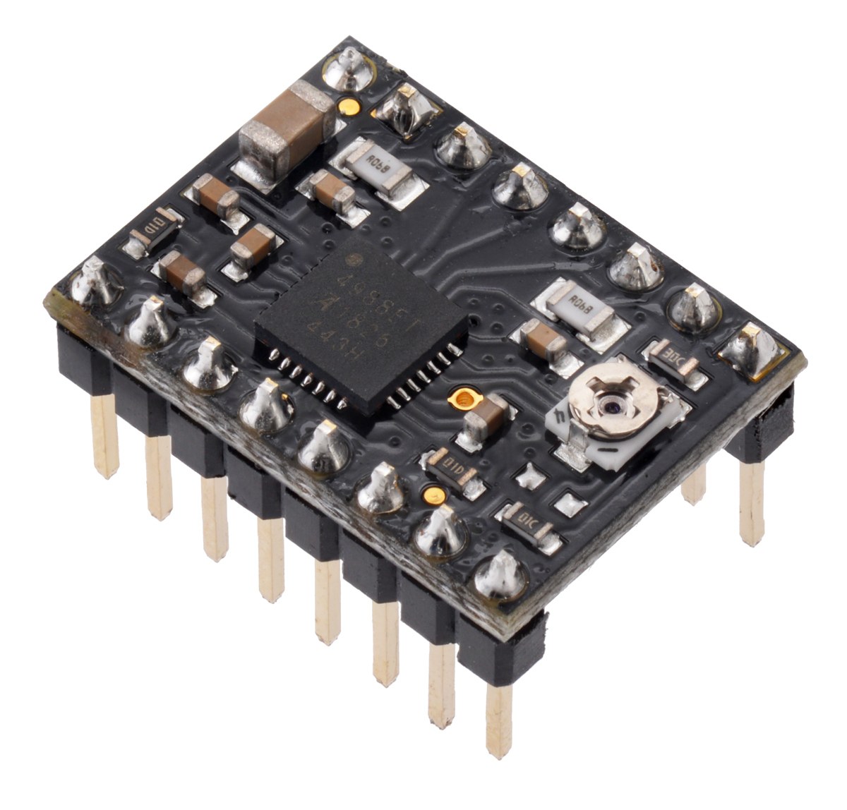
For the current Black Edition carrier, RCS = 0.068 Ω. A target limit of 1.00 A therefore gives 8 × 1.00 × 0.068 = 0.544 V, normally rounded to 0.54 V at the meter.
A legacy carrier with 0.050 Ω sense resistors gives 8 × 1.00 × 0.050 = 0.400 V. Applying 0.54 V to that older resistance would set roughly 1.35 A, not 1.00 A. Board color alone is not a universal identification method for clone modules; read the resistor marking, schematic or vendor documentation for the exact carrier.
Translate a full-step coil reading correctly
In full-step mode, the A4988 energizes both coils at approximately 70% of Imax. If a meter in series with one stationary coil reads 0.70 A, the configured current limit is about 0.70 / 0.70 = 1.00 A.
If the intended full-step coil current is 1.00 A, the limit must instead be near 1.00 / 0.70 = 1.43 A. With 0.068 Ω resistors, that corresponds to about 8 × 1.43 × 0.068 = 0.78 V. Pololu rounds the same practical case to a 1.4 A limit and 0.77 V.
Do not put the meter at the motor power supply and call that coil current. The A4988 and motor winding behave like a switching step-down system; supply voltage, duty cycle and winding voltage make input current different from the controlled coil current.
Current limit is not thermal capability
The A4988 IC is rated up to 2 A per coil, but a small carrier cannot necessarily dissipate the heat required to deliver that continuously. Pololu reports about 1.2 A per phase in full-step mode for the four-layer Black Edition without a heat sink or forced air, compared with about 1 A for its original two-layer board under the same broad conditions.
That thermal observation does not replace temperature validation in the actual enclosure. Airflow, ambient temperature, copper beneath the module and step pattern all change dissipation. The chip can also become hot enough to burn skin before its thermal shutdown protects it.
Protect VMOT before tuning
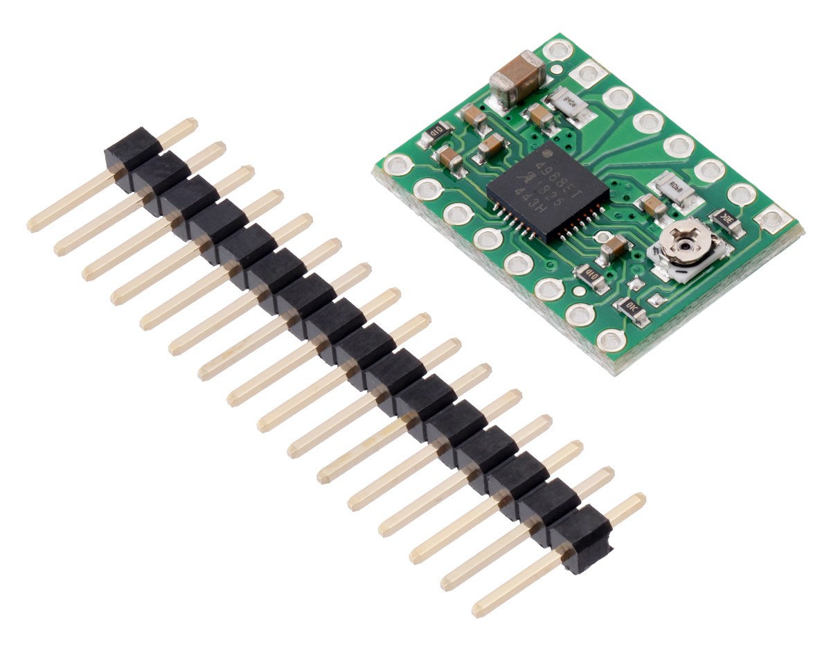
Pololu specifies 3 V to 5.5 V on VDD and 8 V to 35 V on VMOT. Its low-ESR ceramics and supply leads can form an LC circuit that produces a damaging spike, even from a nominal 12 V source. The carrier documentation recommends at least 47 µF of electrolytic capacitance across VMOT and ground close to the board.
Never connect or disconnect the motor while the driver is powered. Also tie the floating RESET input high—Pololu suggests linking it to the adjacent SLEEP pin—unless firmware controls it deliberately. STEP and DIR should not float.
A compact setup sequence
- Identify the exact carrier and its
RCSvalue. - Choose Imax from the motor’s per-phase current rating and the carrier’s realistic thermal envelope.
- Calculate VREF, power logic and motor rails, and measure VREF relative to ground while adjusting carefully.
- With power removed, connect the motor. Then verify coil current or temperature under the real stepping mode and load.
- If full-step coil current is the measurement, divide it by about 0.70 before comparing with Imax.
This calculation is specific to the A4988 and the documented carrier resistance. It should not be copied to a DRV8825 current-limit setup, which uses a different relationship and board implementation.