An ACS72981 carrier does not have one universal conversion formula. The chosen suffix fixes the supply range, current direction, zero-current output and sensitivity. Pick the board before writing the ADC code; otherwise a correct-looking formula can report the wrong sign or scale.
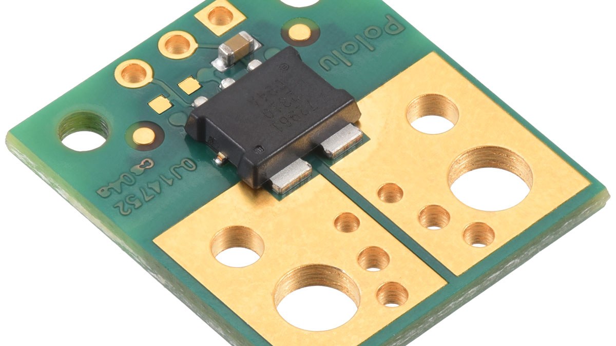
Featured image: Pololu.
The family uses a Hall-effect sensor with an electrically isolated primary current path. Pololu lists about 0.2 mΩ typical conductor resistance, 250 kHz analog bandwidth and less than 2 µs response time for its ACS72981 carriers. Those numbers describe the sensing path, but the output still has to fit the microcontroller’s ADC input range.
Direction changes the zero point
A bidirectional 5 V ±50 A version uses a 2.5 V zero-current point and 40 mV/A sensitivity. That leaves room above and below zero for positive and negative current. The 5 V unidirectional 0–50 A version instead starts at 0.5 V and uses 80 mV/A, spending more of the output range on one current direction.
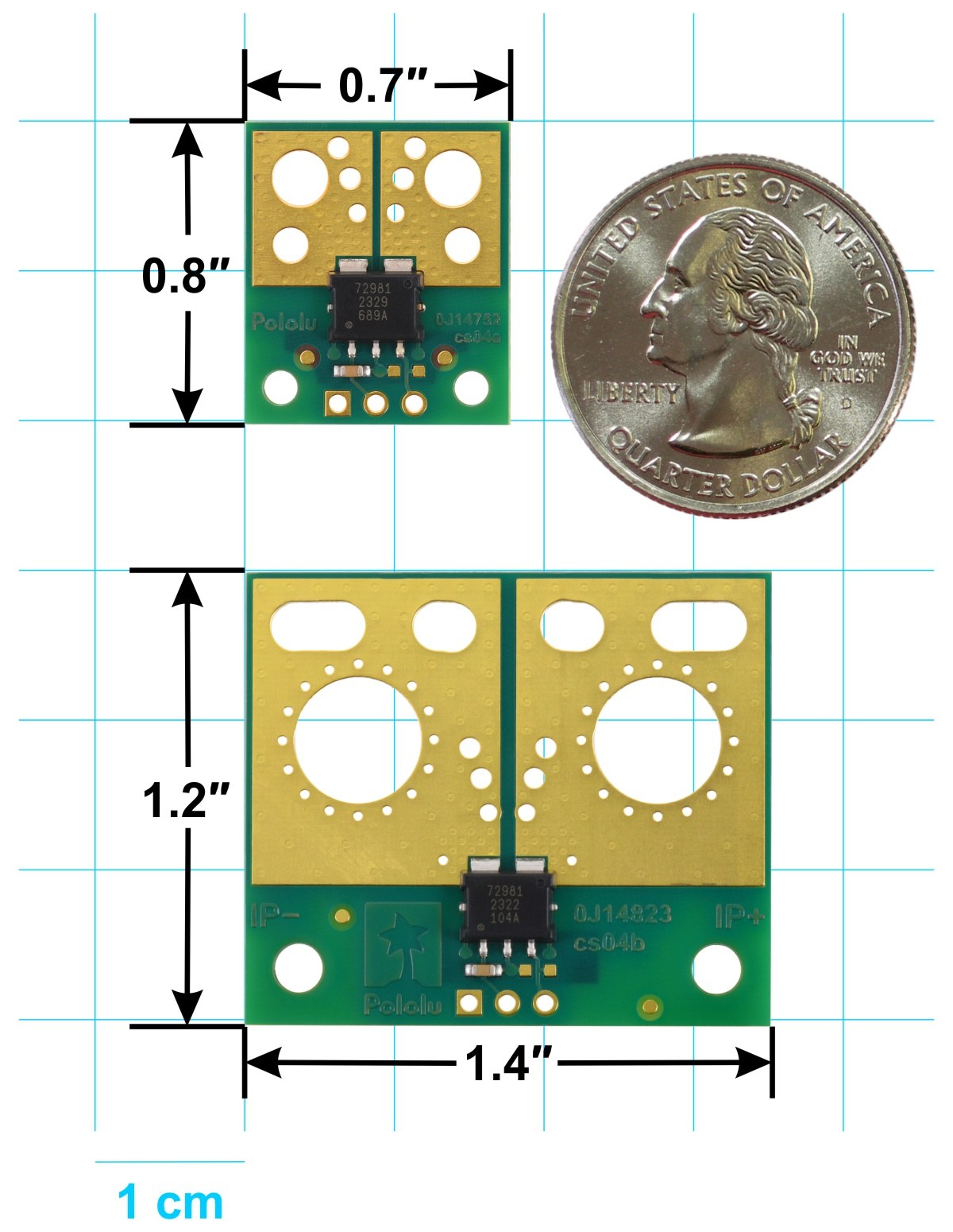
For Pololu item 5264, the nominal transfer is:
current (A) = (VOUT − 0.5 V) ÷ 0.080 V/A
At 25 A, that produces 2.5 V. At 50 A, it produces 4.5 V. A nominal 10-bit ADC using a 5.0 V reference would therefore return about 512 counts at 25 A and 921 counts at 50 A, before offset, sensitivity, reference and quantization error are considered.
Match the output to the ADC rail
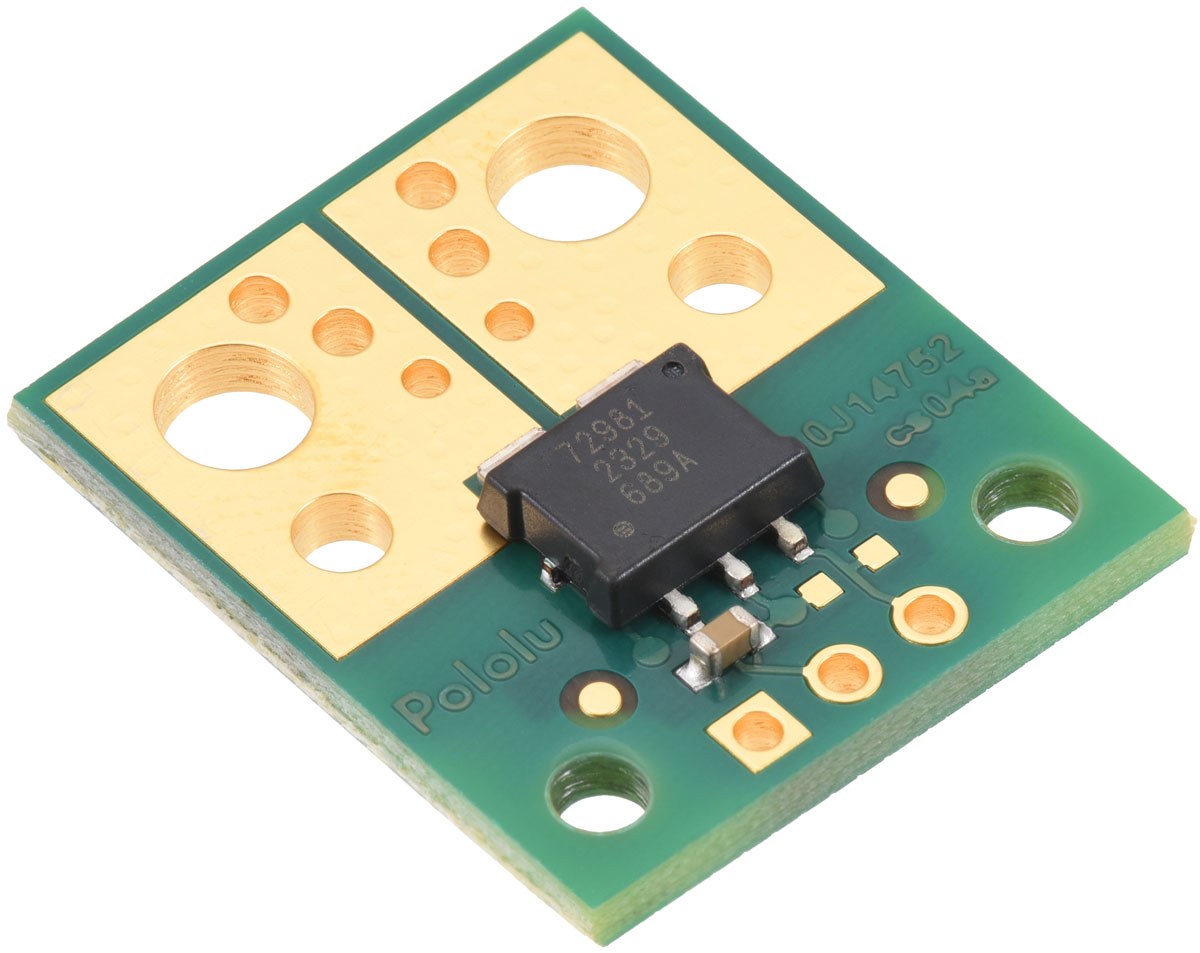
The 050U5 carrier is specified for a 4.5–5.5 V supply. Its output can exceed a 3.3 V-only ADC input well before full current, so direct wiring to a 3.3 V microcontroller is not automatically safe. A 3.3 V ACS72981 variant, or a properly designed attenuation and protection stage, avoids relying on an overvoltage-tolerant pin that may not exist.
Do not substitute the supply voltage for the ADC reference in the code unless they are physically the same measured node. The same reference dependency appears in MCP3008 code-to-voltage conversion. The general conversion is VOUT = code × VREF ÷ ADCmax, followed by the variant-specific offset and sensitivity. Arduino’s analogRead() reference also notes that resolution varies by board; hard-coding 1023 is correct only for a 10-bit conversion.
Range is also a resolution choice
A wider current range reduces mV/A sensitivity. That may prevent clipping on a high-current load, but it also gives fewer ADC counts per ampere. Choose the narrowest range that still covers normal current, startup surge and plausible fault current, while keeping the sensor output inside the ADC’s absolute input limits.
The low-resistance primary path limits dissipation but does not eliminate it. At 50 A and 0.2 mΩ, the sensor IC path dissipates about 0.5 W by P = I²R. PCB copper, terminals, airflow and the manufacturer’s thermal limits still control whether a carrier is suitable for sustained high current.