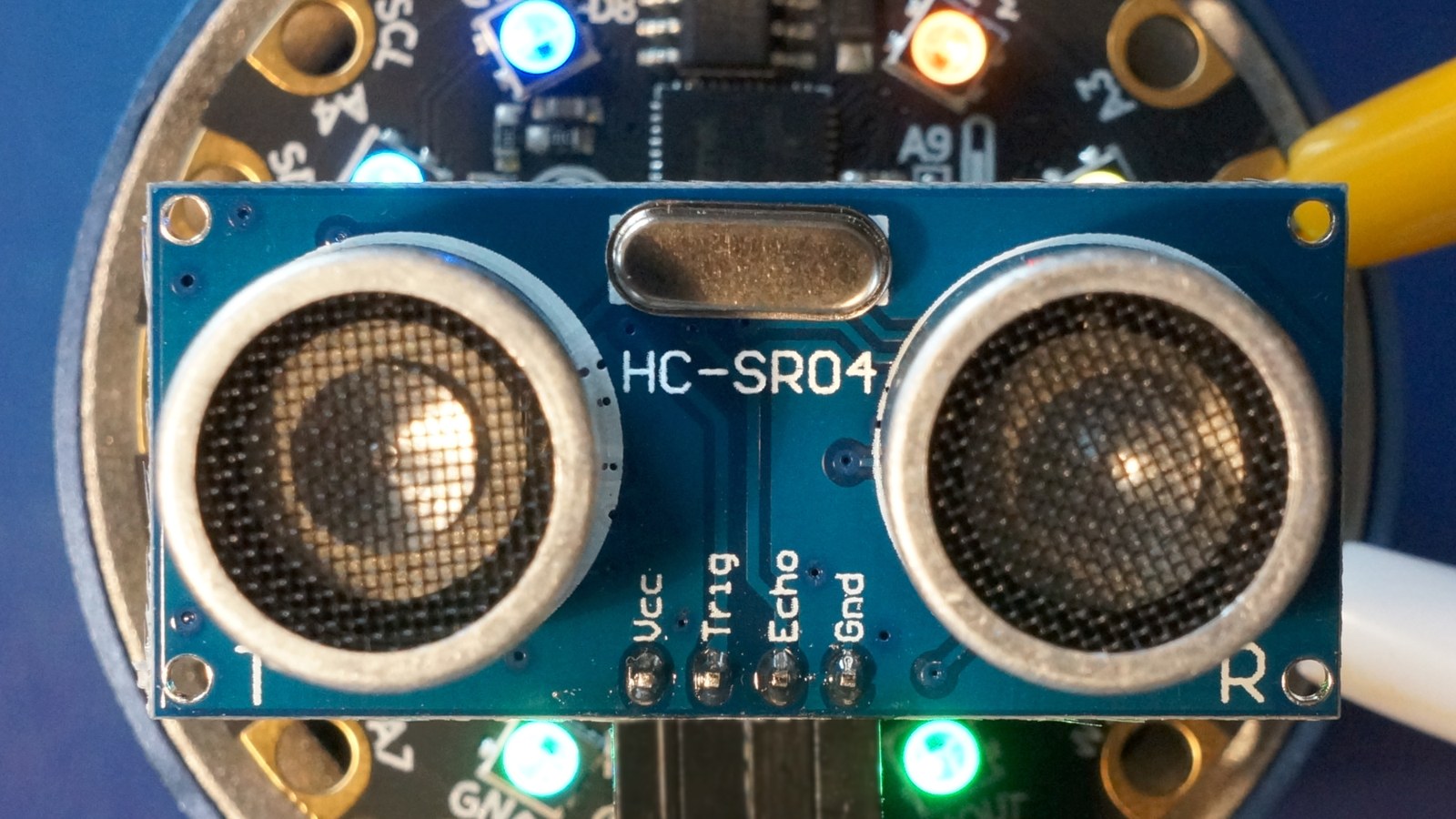
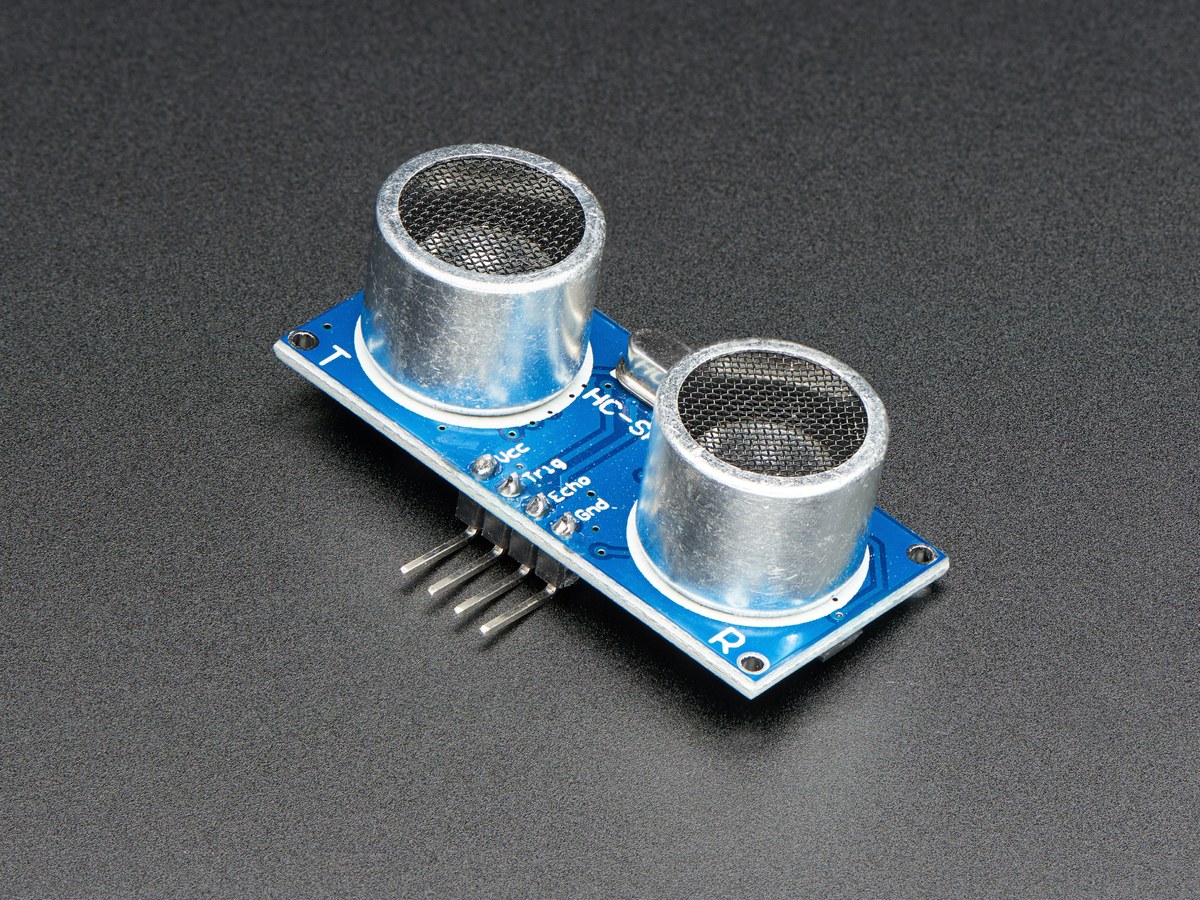
An HC-SR04 should not have its Echo pin connected directly to a Raspberry Pi, Pico or other 3.3 V-only GPIO. The sensor is normally powered from 5 V, and Adafruit specifies its Echo output as 5 V logic. The safe fix is a divider on Echo; the 3.3 V trigger line can still drive Trig.
Featured image: Adafruit.
Wire the divider at the receiving pin
Place one 10 kΩ resistor between Echo and the GPIO input node. Place the second 10 kΩ resistor between that node and ground. The sensor and controller must share ground.
The divider calculation is:
Vout = Vin × Rbottom / (Rtop + Rbottom)
With 5 V in and two equal 10 kΩ resistors, the input sees 5 × 10/(10 + 10) = 2.5 V. That is high enough to register as logic high on typical 3.3 V GPIO while keeping the 5 V pulse away from the pin.
Check timing before blaming distance math
A high pulse of at least 10 µs on Trig starts a reading. The sensor sends an ultrasonic burst and holds Echo high for the round-trip travel time. Using about 343 m/s for the speed of sound, one centimetre of one-way distance corresponds to roughly 58.3 µs of Echo duration:
distance_cm ≈ echo_time_us / 58.3
The division by two is already built into that constant because sound travels to the target and back. If code applies another division by two, every result will be about half the real distance.
Read the failure pattern
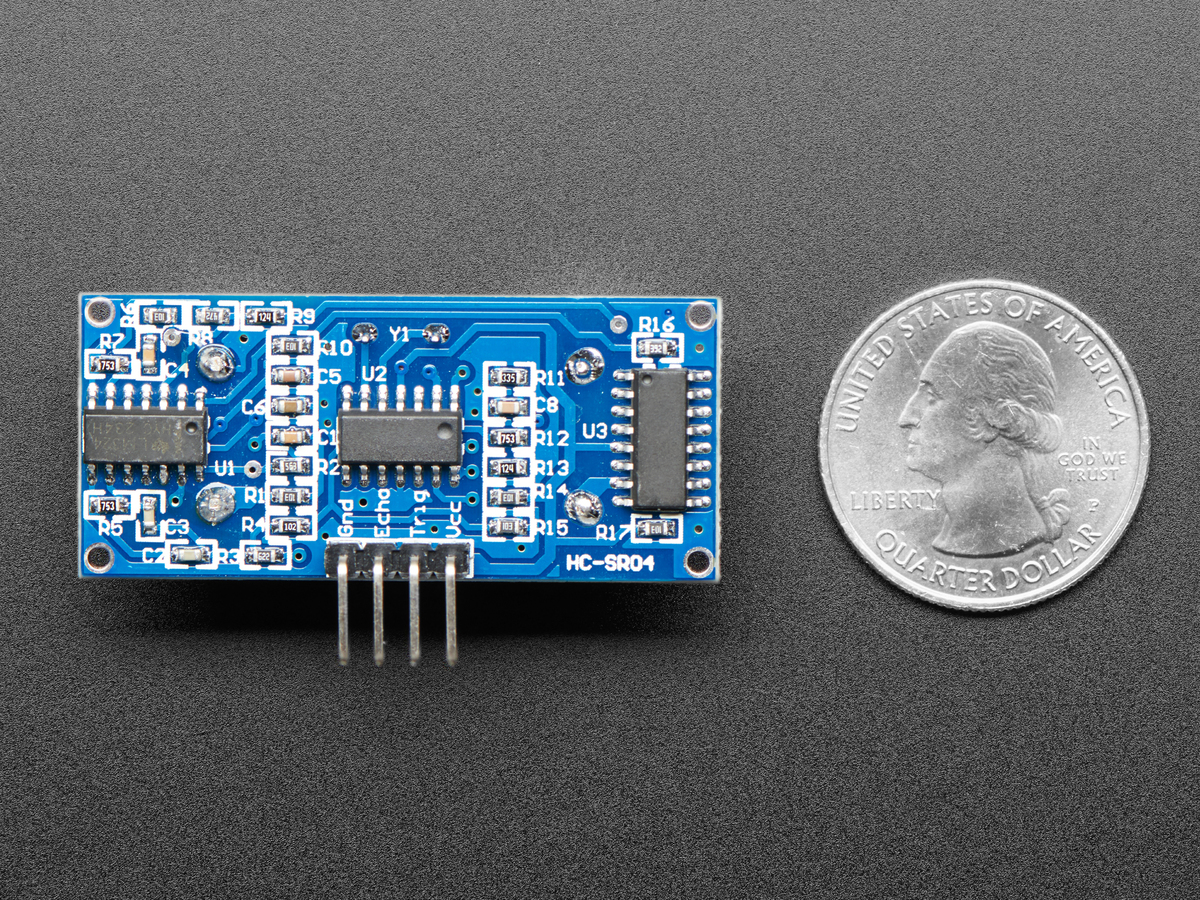
- No Echo pulse: confirm 5 V at VCC, common ground, a 10 µs-or-longer trigger and a timeout in software.
- Fixed or impossible values: verify that the GPIO is connected to the divider midpoint, not directly to Echo or to ground.
- Good nearby readings but poor long-range results: check target angle and surface. Soft, narrow or oblique targets can reflect little energy back.
- Failure below a few centimetres: the module’s commonly published range starts at 2 cm; the transmit burst and receiver recovery limit close-range use.
Do not “fix” weak readings by removing the divider. The resistor pair protects the electrical interface; target geometry and timeout handling belong in separate troubleshooting steps. Also keep the Echo lead short enough that breadboard noise and loose jumpers do not become a second variable. For wider sensor-power problems, see TVG’s robot sensor rail brownout and noise guide.