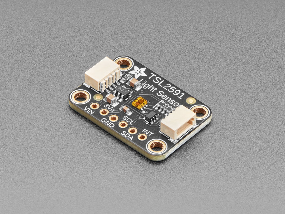
A TSL2591 can report a plausible-looking but unusable lux value when either of its 16-bit light channels clips. The first repair is not a calibration offset: reduce sensitivity by lowering gain, shortening integration time, or both, then wait for a complete new conversion before evaluating the scene again.
The sensor combines a full-spectrum channel with an infrared channel and derives illuminance from their relationship. Because both measurements feed the calculation, saturation in either channel removes information that software cannot restore.
Gain and integration time multiply sensitivity
The TSL2591 provides four gain settings—approximately 1×, 25×, 428× and 9876×—and six integration times from 100 ms through 600 ms in 100 ms steps. Higher gain amplifies the photodiode signal; longer integration accumulates it for more time. Both improve low-light resolution, and both consume headroom in bright light.
A compact control loop should treat saturation as a range-selection event. If a channel approaches its limit, step down gain first when the scene changes quickly; if more headroom is still needed, shorten integration time. In darkness, reverse the order gradually and allow each setting to produce a fresh sample before deciding again.
The clipping limit changes with integration time
The ams data sheet specifies a lower maximum count for 100 ms integration than for longer conversions: about 36,863 counts at 100 ms and 65,535 counts from 200 to 600 ms. Code that checks only for 0xFFFF can therefore miss a 100 ms over-range sample.
That detail also explains why a clipped value need not remain numerically fixed at 65,535. A driver should use the sensor’s documented saturation rule for the selected integration time and inspect the raw full-spectrum and infrared channels, not only the final lux property.
Read only after the new conversion is ready
Changing gain or integration time changes the measurement window; it does not retroactively repair the previous sample. At 600 ms integration, the next valid result inherently takes roughly six times as long to collect as a 100 ms sample. A loop that changes configuration and immediately rereads may classify stale data as the result of the new range.
For a moving robot or flickering light source, the integration window is also temporal averaging. A 600 ms exposure can smooth rapid changes that a 100 ms exposure would preserve. The appropriate setting therefore depends on both brightness and required response time, not only on whether the ADC clips.
Use the two raw channels as the diagnostic
- Both channels near their limits: lower gain, then shorten integration if necessary.
- Full-spectrum high, infrared lower: preserve both raw values and verify the driver’s lux-validity check before accepting the result.
- Counts near zero: increase integration time or gain one step at a time.
- Values change immediately after reconfiguration: wait at least the selected integration interval and read again.
Adafruit’s CircuitPython driver exposes the raw infrared and full-spectrum values alongside gain and integration-time controls. That makes a small automatic-ranging loop possible without hiding the reason for each range change. The result is more defensible than applying an arbitrary multiplier to a lux value already derived from clipped inputs.
When comparing the sensor with another instrument, first lock the gain, integration time, geometry and light source. Otherwise a calibration exercise can mix range changes with real optical differences—the same measurement-first principle behind TVG’s probe-loading guide, applied here to a digital optical front end.