A DC motor that draws 200 mA while spinning freely can demand several amperes when its shaft cannot turn. Selecting a motor driver or power supply from the no-load current is therefore one of the fastest ways to produce resets, overheated connectors, or a driver that enters protection as soon as a robot starts moving.
The correct starting point is stall current: the current at zero speed, when there is no back electromotive force opposing the supply. It is not a normal operating target, but it defines the electrical stress during a jam and approximates the first instant of a hard start.
A worked example with two 12 V gearmotors
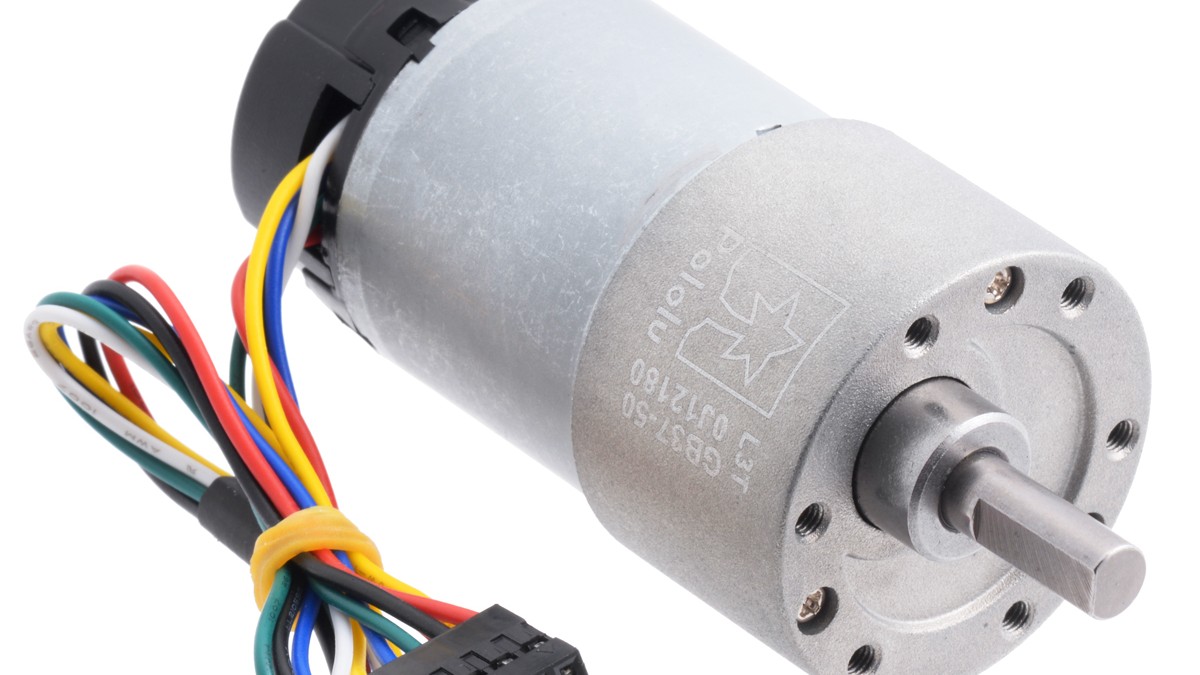
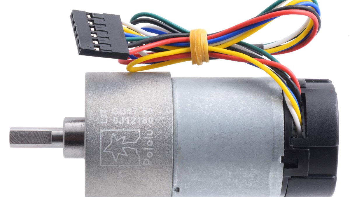
Pololu specifies its 12 V, 50:1 37D gearmotor at 200 RPM and 0.2 A with no load. The same product page lists an extrapolated stall current of 5.5 A and stall torque of 21 kg·cm. Two identical motors can therefore demand 2 × 5.5 A = 11 A if both are stalled or commanded from rest into a sufficiently heavy load.
That 11 A is the motor branch alone. Add the controller, radio, sensors, lights, and the losses of any DC-DC converter. If a 5 V computer consumes 2 A through a 90%-efficient converter from a 12 V bus, its approximate bus current is (5 V × 2 A) ÷ (12 V × 0.90) = 0.93 A. The combined short peak is then close to 12 A before margin.
Peak rating and continuous rating answer different questions
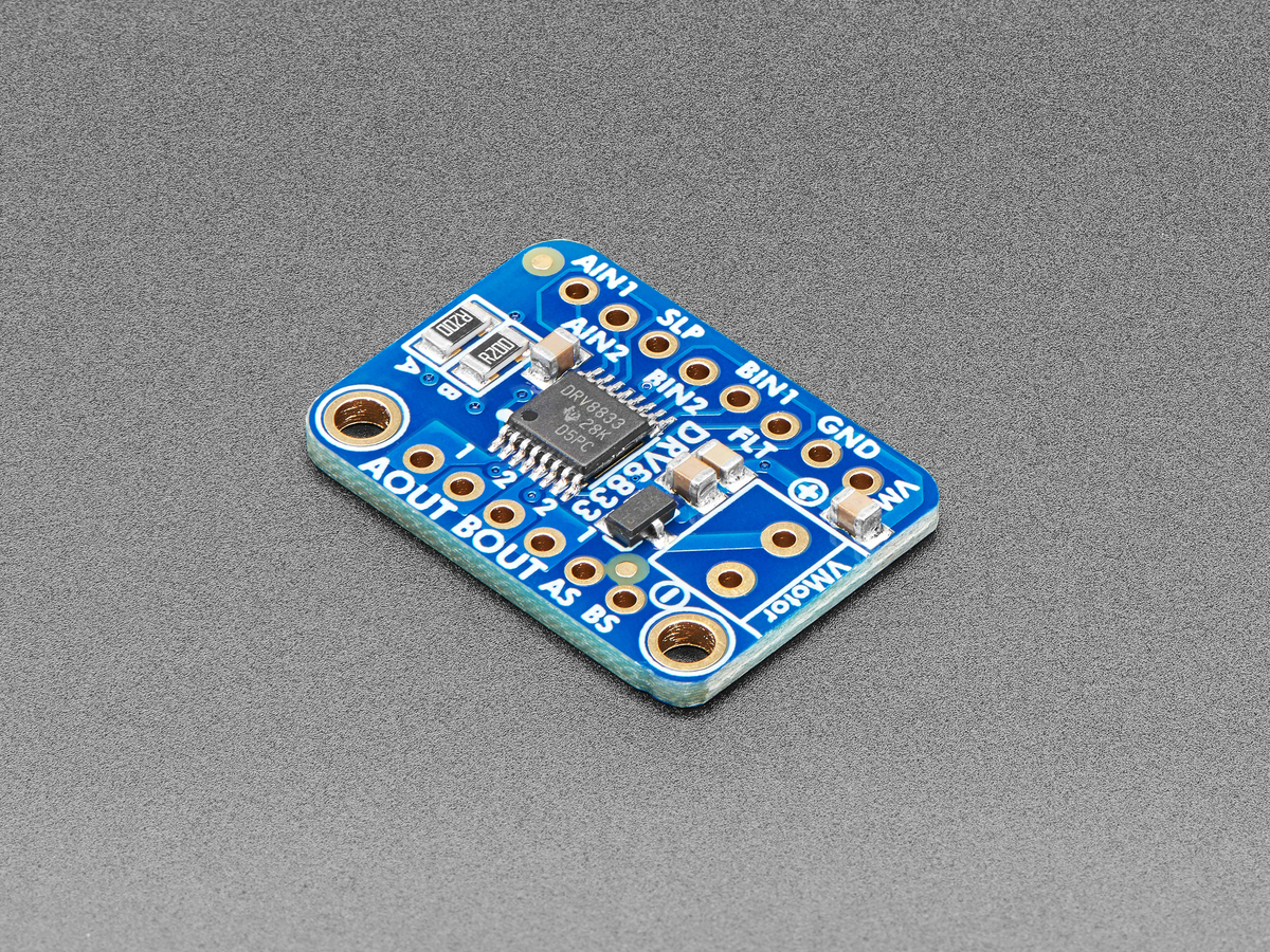
A driver’s peak-current number indicates whether it can survive a brief surge under specified cooling and timing conditions. Its continuous rating is governed by MOSFET resistance, switching losses, board copper, airflow, and the temperature limit. A data sheet that promises 20 A for a few milliseconds does not imply 20 A indefinitely.
Check the rating per channel. A dual driver advertised with a combined number may have a lower limit for each motor, and both channels heat the same board. Protection behavior also matters: cycle-by-cycle current limiting, latched overcurrent shutdown, and thermal retry produce different robot behavior during a jam.
The motor has its own thermal limit. Pololu warns that stalls can damage windings and brushes on the order of seconds and gives 25% of stall current as a general recommendation for brushed DC operation. For the 5.5 A example, 25% is about 1.38 A. That is a guideline rather than a universal continuous-current rating, but it shows why a driver sized only to the motor’s ordinary cruise current can leave too little fault margin.
Power-supply sag is part of the calculation
The battery or supply must deliver the peak without collapsing below the driver, regulator, or computer input threshold. Every battery cell, protection board, fuse, wire, connector, switch, and PCB trace contributes resistance. The drop is Vdrop = I × R.
If the complete source and delivery path measures 0.15 Ω, an 11 A motor surge drops 1.65 V before accounting for the driver’s switching path. A nominal 12 V bus reaches only 10.35 V at the driver input. A partly discharged battery with higher internal resistance will sag farther. If logic shares that bus through an inadequate regulator, the result can be a controller brownout precisely when the motors need maximum torque.
A bench supply can create a different failure. If its current limit is set below the start surge, it may enter constant-current mode and pull the bus voltage down. That is not proof the motor needs only the displayed limited current; it is evidence that the source is clipping the demand.
Read the performance curve, not only the endpoint
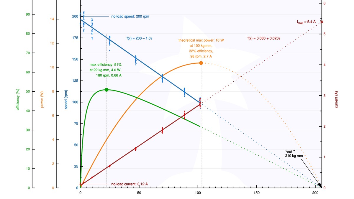
The Pololu Rev. 1.2 datasheet shows the 12 V performance curve for items 4743 and 4753. Maximum efficiency occurs around 22 kg·mm, 180 RPM, and 0.66 A. The theoretical maximum-power point appears around 100 kg·mm, 98 RPM, and 2.7 A. These points are more informative for ordinary operation than the extrapolated stall endpoint, but the stall current still sets the electrical fault boundary.
Motor current generally rises with torque while speed falls. A robot that cruises comfortably on a stand can move much closer to the high-current region on carpet, a slope, or during a pivot turn. Mechanical gearing, wheel diameter, vehicle mass, and acceleration command determine where it operates on the curve.
A defensible sizing sequence
- Take stall current from the motor data sheet at the actual bus voltage.
- Multiply by the maximum number of motors that can start or jam together.
- Choose a driver whose per-channel peak limit can tolerate that event and whose continuous thermal rating covers the measured operating current.
- Add nonmotor loads and conversion losses to the supply budget.
- Estimate voltage sag from source and path resistance, then compare the remaining voltage with every brownout threshold.
- Provide a fault response: current limiting, a fuse, a timeout, thermal monitoring, or a combination appropriate to the mechanism.
Oversizing only the power supply is not enough. The battery connector, wiring, PCB copper, motor driver, and protective device all carry the same surge. A robust design treats stall current as a system-level boundary and normal running current as a separate thermal operating point.