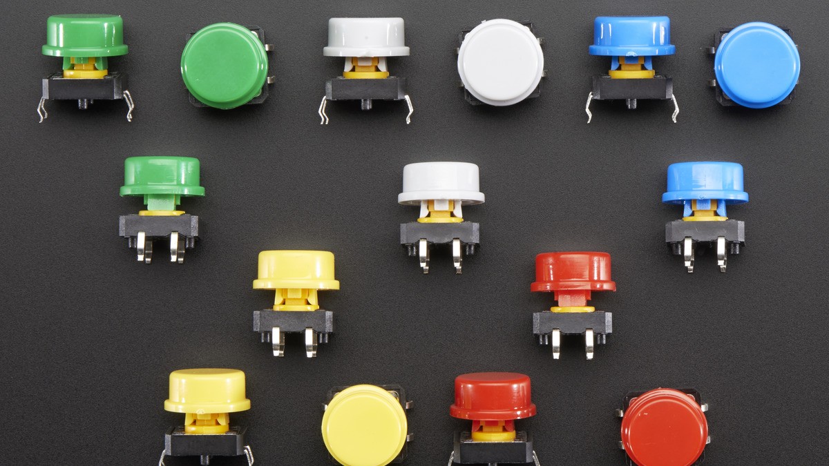
One press that produces two counts, two menu steps, or several interrupts is often a contact-bounce problem, not a bad loop or a failing microcontroller. The metal contacts inside a mechanical switch do not always settle in one clean transition. They can make and break contact repeatedly while the logic input is fast enough to register every edge.
Texas Instruments’ SCEA094 application brief puts the timing mismatch in perspective: switch contacts can bounce for hundreds of microseconds, while logic devices respond in nanoseconds. Circuit Cellar notes that the complete disturbance commonly occupies milliseconds. The right fix depends on whether the input is read by firmware, used as an interrupt, or must remain valid before software starts.
First separate bounce from electrical noise
Bounce usually clusters around the instant a button is pressed or released. Electromagnetic noise can appear while a motor, relay, or switching regulator runs, even when nobody touches the switch. A floating input can change state at any time. These faults can look similar in a counter, so inspect the timing before changing the code.
A logic analyzer or oscilloscope should show a burst of transitions near the mechanical event if bounce is responsible. If transitions track motor commutation or a long cable, address grounding, routing, shielding, and input bias as well. Debounce code should not be used to hide a power-integrity or wiring fault.
Software debounce is usually the simplest choice
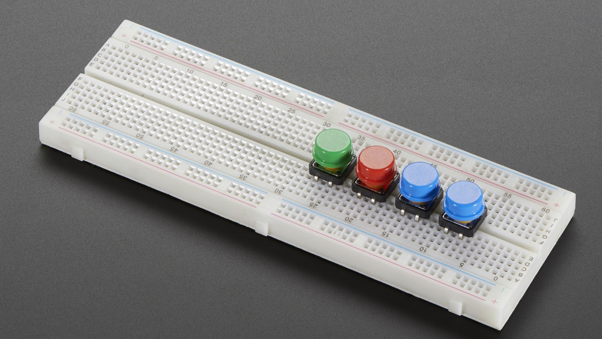
For a button read by a microcontroller, firmware can wait for the state to remain unchanged before accepting it. A nonblocking implementation stores the last raw state and the time it changed. The program accepts the new stable state only when the same reading persists for the chosen interval. Using a monotonic millisecond counter avoids freezing unrelated tasks.
A 10 ms interval is a reasonable starting point for an ordinary human-operated button, but it is not universal. The interval should be longer than the observed bounce and shorter than the response time the interface requires. An emergency stop, encoder, or high-rate pulse input should not inherit a generic 50 ms delay from a user-interface example.
Software debounce has two important limits. It cannot protect logic that acts before firmware runs, and an interrupt can still be invoked repeatedly unless the interrupt handler masks subsequent edges or hands them to a timed state machine. It also does not repair an input that lacks a defined pull-up or pull-down state.
Calculate an RC network instead of guessing
An RC network slows the voltage change seen by the input. Its time constant is τ = R × C. A 100 kΩ resistor and 0.1 µF capacitor produce 10 ms; 10 kΩ with 1 µF produces the same value. TI’s table uses these combinations and recommends choosing a time constant around half the desired debounce time.
The resistor also sets current and power when the switch closes. For a pull-up, P = V²/R. At 5 V and 10 kΩ, the resistor dissipates 2.5 mW and the closed-switch current is 0.5 mA. Raising the resistance reduces current but makes input leakage and contamination more important. Increasing capacitance can make the component physically larger and increase inrush through the contact.
Why a Schmitt trigger matters with slow edges
A plain RC filter can leave a CMOS input moving slowly through its threshold region. Noise riding on that ramp may create more than one transition, and some logic families draw extra current when an input sits between valid low and high levels. A Schmitt-trigger input uses separate rising and falling thresholds, adding hysteresis so the filtered signal changes state once.
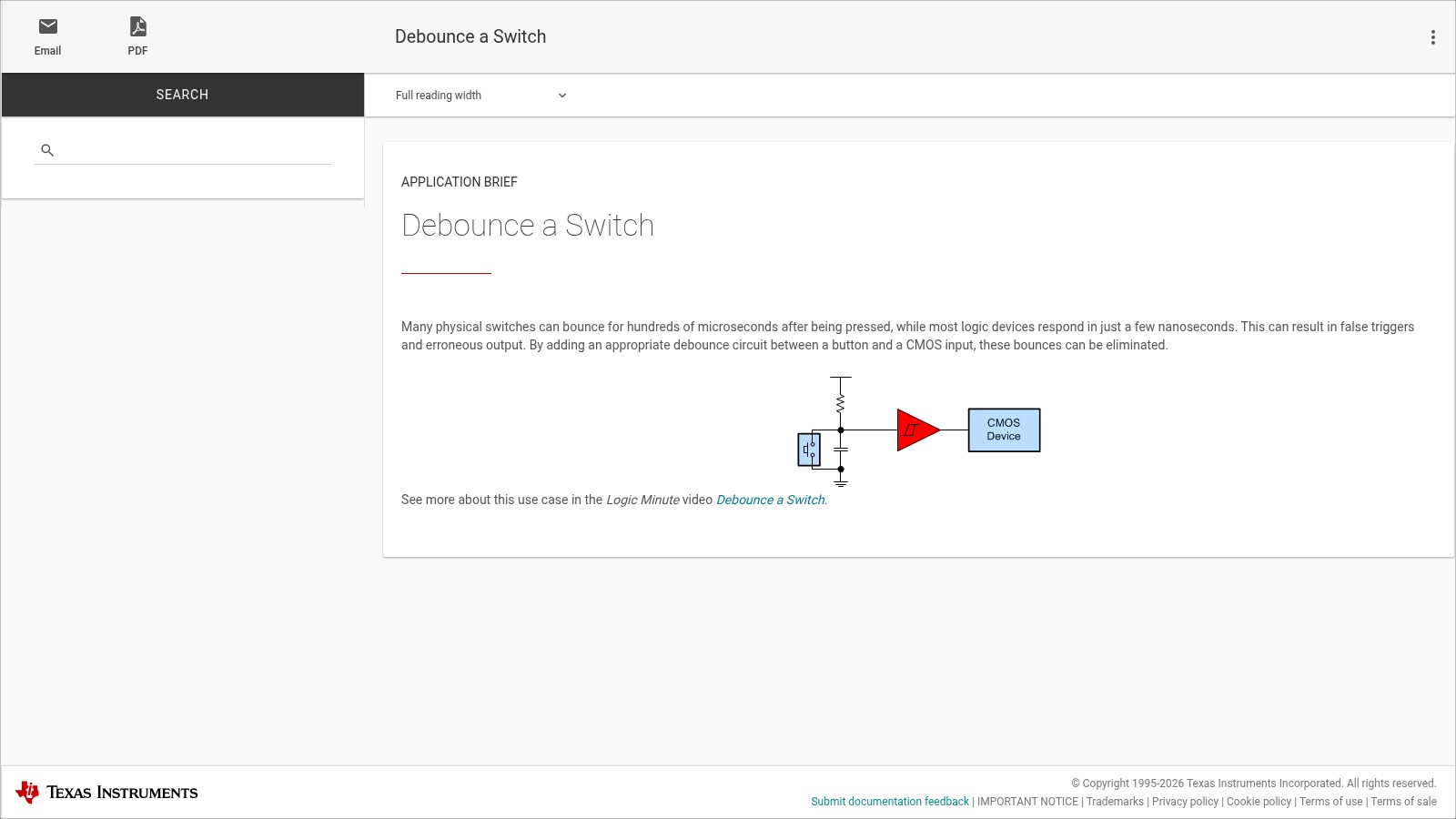
TI lists the SN74LVC1G17 as a single noninverting Schmitt-trigger buffer operating from 1.65 V to 5.5 V, and the lower-power SN74AUP1G17 from 0.8 V to 3.6 V. The supply range must match the system, and the switch network must respect the buffer’s input limits. A resistor-capacitor network followed by a Schmitt input is a strong choice for reset lines, wake inputs, hardware counters, and other paths that must be clean before application software can intervene.
Choose by the consequence of a false edge
Use software when the signal is an ordinary user input and firmware already owns the event. Add hardware when the edge reaches reset, power control, a counter, or an interrupt that cannot tolerate repeated activation. Combine hardware and software when a long cable or harsh electrical environment demands both a conditioned signal and application-level state validation.
The interval or component values should come from the observed switch and the required response, not from a universal recipe. The practical end state is one accepted event per intentional press, with a defined idle voltage and no slow, ambiguous transition at the receiving logic input.