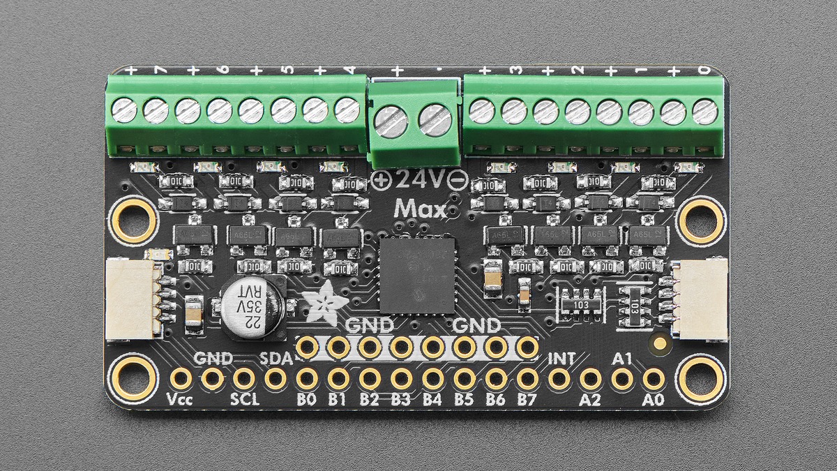
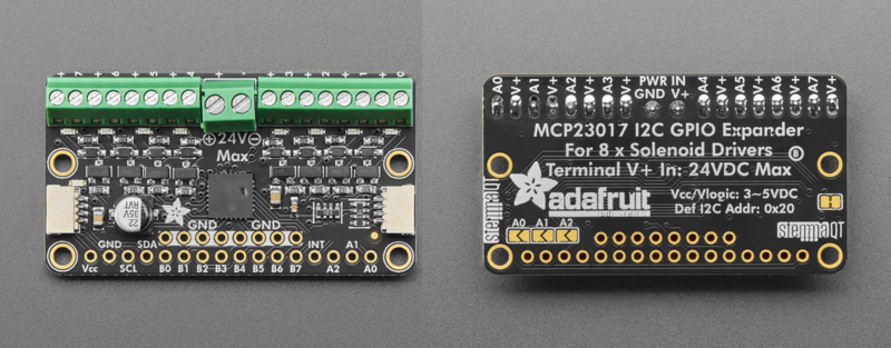
Adafruit’s I2C to 8 Channel Solenoid Driver can switch eight DC loads from one MCP23017-controlled board, and as many as eight boards can share the bus. That creates a logical ceiling of 64 outputs, but it does not create a 64-solenoid power supply. Coil current, wire loss, connector capacity and simultaneous duty cycle still have to be budgeted outside the I2C address plan.
Featured image: Adafruit.
Keep logic power and coil power separate
The board’s Vcc pin follows the microcontroller logic level: 3 V for a 3 V controller or 5 V for a 5 V controller. The center V+ terminal supplies the solenoids and accepts 3 V to 24 V DC maximum. Ground is common between the logic and load sides.
That separation prevents the microcontroller rail from carrying coil current, but it does not isolate the grounds. A loose ground, undersized return conductor or large coil-current step can still move the controller’s reference and disrupt I2C communication. Bring the high-current return to the supply with an appropriately sized path rather than routing it through a thin breadboard jumper.
Calculate the load before choosing the supply
For a coil specified by resistance, estimate its steady current with I = V/R. Eight 12 V coils measuring 24 Ω each draw about 0.5 A per channel and 4 A if all eight remain energized. The supply should cover the simultaneous current plus margin for tolerance, wiring loss and other loads on the same rail.
If the solenoid data sheet specifies current directly, use that value instead of a room-temperature resistance estimate. Copper resistance rises as a coil heats, while pull-in behavior can require a different voltage or duty pattern from the holding state. The relevant design case is the maximum number of channels that software can energize at once, not the average count during a demonstration.
Read the MOSFET numbers correctly
Each output uses an AO3406 N-channel MOSFET. Adafruit lists 30 V drain-to-source rating, 3.6 A peak current and 70 mΩ on-resistance. The 3.6 A figure is not permission to run eight channels continuously at 3.6 A: peak transistor current, terminal heating, board copper, ambient temperature and total simultaneous dissipation are separate limits.
At 0.5 A, a 70 mΩ channel dissipates about I²R = 0.0175 W in the MOSFET under the stated resistance assumption. At 2 A, that rises to 0.28 W. Because loss scales with current squared, doubling current quadruples conduction heating. Designers should leave voltage and thermal margin rather than matching a coil to the absolute headline rating.
Flyback protection changes the turn-off path
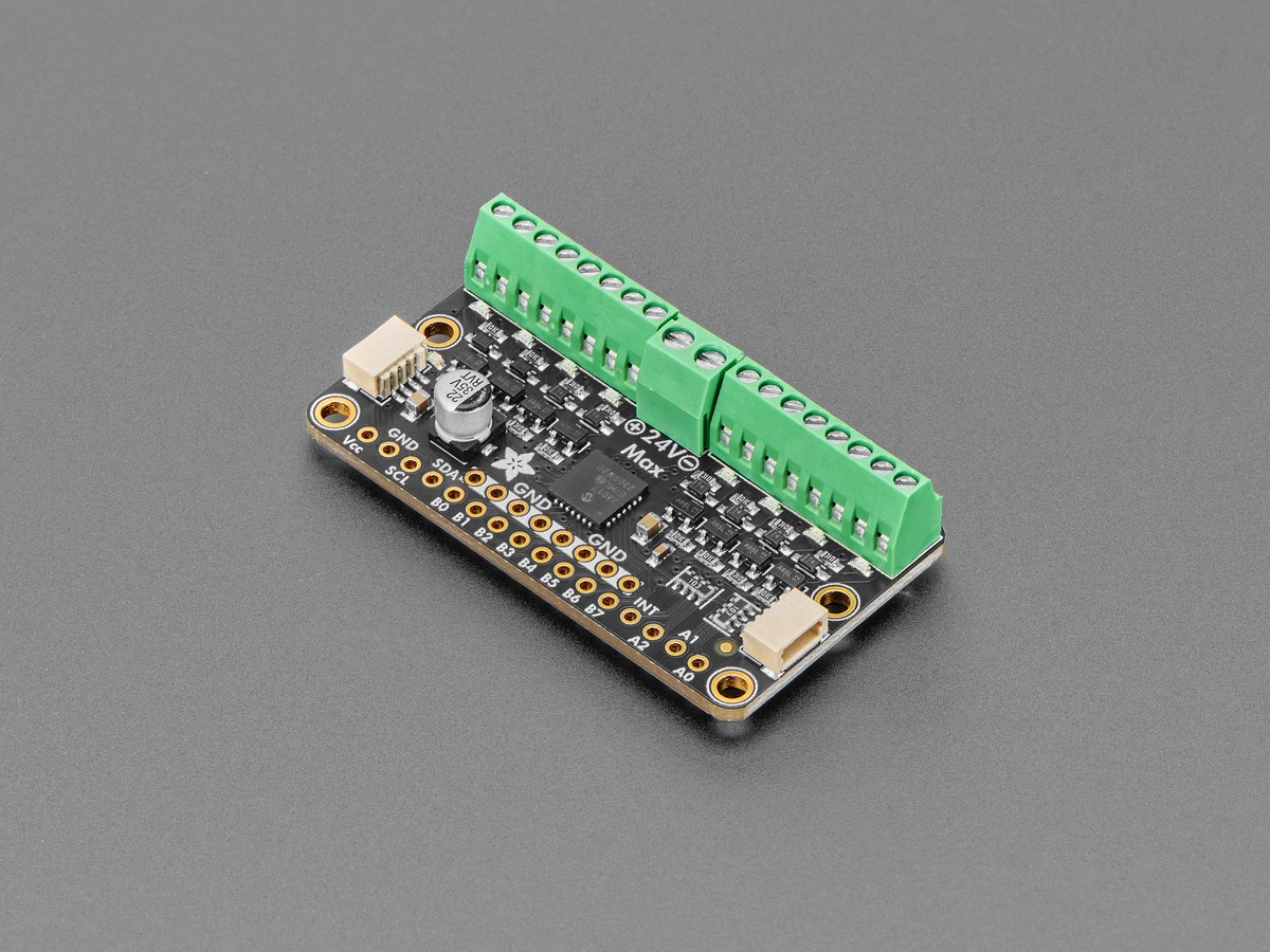
Each channel includes a flyback diode. When a MOSFET turns off, the coil current cannot stop instantly; the diode gives that current a local recirculation path and prevents the drain voltage from rising without control. The protection is essential for an inductive load, but a simple diode also produces a relatively low clamp voltage, so current decays more slowly than it would with a higher-voltage zener or TVS clamp.
Texas Instruments notes that higher-voltage clamping can be used when rapid solenoid de-actuation is required. That is a different driver design decision, not a reason to remove the board’s diode. For a mechanism where release time is critical, verify the actual coil-current decay and mechanical release specification rather than assuming every protected driver has the same timing.
Addressing eight boards is deterministic
The default I2C address is 0x20. Three address bits add 1, 2 and 4, producing the range 0x20 through 0x27. For example, closing A2 and A0 adds 4 + 1, so that board uses 0x25. Eight addresses multiplied by eight output channels gives the 64-output logical maximum.
The board also includes 10 kΩ pull-ups on SDA and SCL. Chaining boards and cables adds bus capacitance, so address uniqueness does not guarantee signal integrity. If communication becomes intermittent as the chain grows, inspect rise time, cable length, grounding and the effective parallel pull-up resistance before changing software.
A commissioning order that protects the mechanics
- Connect logic power and confirm the expected I2C address with coil power off.
- Verify every output initializes off before enabling the load supply.
- Connect one coil and confirm its rated voltage, current and polarity at the terminals.
- Energize channels in the maximum intended combination while measuring the load supply at the board.
- Check connector, wire and board temperature over the real duty cycle.
- Only then add more boards, with a documented address and current allocation for each one.
This sequence does not replace the solenoid manufacturer’s duty-cycle or thermal limits. It separates I2C configuration from the higher-energy load path so an address error is less likely to become an unexpected mechanical actuation.