A 5 V buck converter that produces the correct voltage with no load but sags or resets a board when current rises is often running out of input headroom. Measure input and output simultaneously at the converter pins under real load. If the input falls toward the required output plus dropout voltage, the regulator is no longer able to hold 5 V—even when the battery measured comfortably above 5 V at rest.
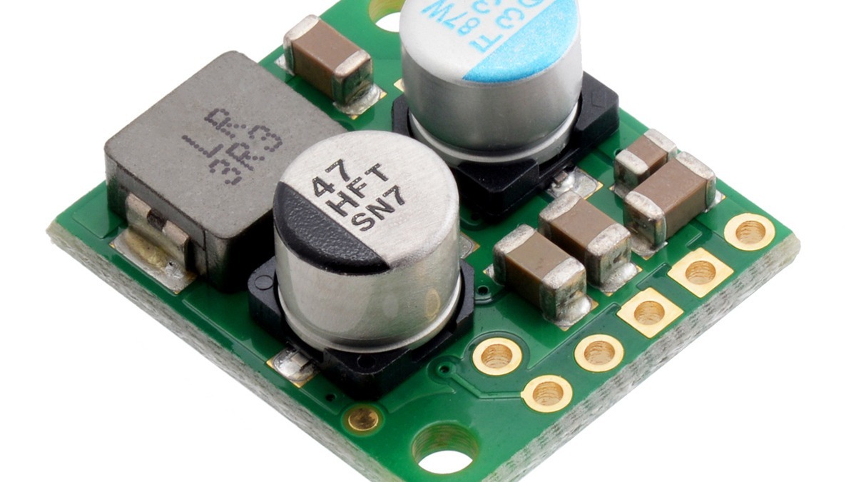
Featured image: Pololu.
Start with the loaded input
The key test is not open-circuit battery voltage. It is loaded voltage at VIN. Wiring, connectors, switches, protection devices and the battery’s own internal resistance all contribute to the difference:
VIN(at converter) = Vsource(open circuit) − Iload × RpathA useful pass condition is VIN ≥ VOUT + Vdropout at the intended current, including the worst battery state and cable temperature. Because dropout generally rises with output current, a supply can pass at idle and fail exactly when a radio, motor, display or processor enters a high-current state.
Dropout is a load-dependent number
Pololu specifies its 5 V D36V28F5 module for a nominal input range of 5.3 V to 50 V, but explicitly makes the lower limit subject to dropout. The module page defines dropout as the minimum input-to-output difference needed to maintain the target output and shows that the required difference increases approximately with load. Its family graph puts the 5 V version near roughly 0.8 V at 1 A and about 1.3 V at 4 A; those values are graph readings, not guaranteed limits.
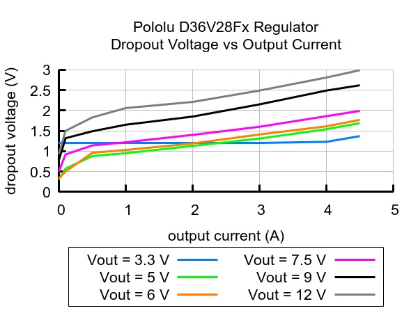
For this example, a 5 V rail at 1 A may therefore need close to 5.8 V at the converter input. If a battery reads 6.2 V with the load disconnected but the wiring path totals 0.5 Ω, the path loses 0.5 V at 1 A and delivers only 5.7 V. That is below the approximate headroom indicated by the graph, so output sag would be expected. The arithmetic localizes the fault without assuming the module is defective.
Texas Instruments’ low-dropout buck note explains the underlying limit. A buck converter approaching its maximum duty cycle cannot keep increasing switch on-time indefinitely. Conduction losses in the switch and inductor then create a minimum difference between input and output. “100% duty cycle” also does not imply zero dropout; resistance still produces voltage loss under current.
Measure at the pins, not at the battery
Use two meter channels or an oscilloscope if available. Place one pair of probes directly between the regulator’s VIN and GND pins, and the other directly between VOUT and GND. Start with no load, then apply the actual load or a controlled electronic load in steps. Record input voltage, output voltage and current together.
- Input and output fall together: suspect battery sag, cable resistance, a weak connector, a protection FET or an undersized switch before blaming the converter.
- Input remains above the required headroom but output falls: check current limit, thermal shutdown, assembly damage and output-capacitor requirements.
- Output is initially correct, then decays as the board heats: compare the load with the converter’s thermal current curve; the headline current is not a universal continuous rating.
- The rail pulses or repeatedly restarts: look for current-limit hiccup behavior or a downstream load that retries after undervoltage.
Do not confuse current rating with guaranteed operation
The D36V28F5 listing calls 3.2 A a typical maximum at 36 V input. The same page says the family’s continuous capability ranges roughly from 2.5 A to 4 A depending on version, input voltage, ambient temperature, airflow and heat sinking. It also gives typical efficiency of 80% to 90% and about 500 kHz switching under heavy load. None of those typical values guarantees a particular build at a particular temperature.
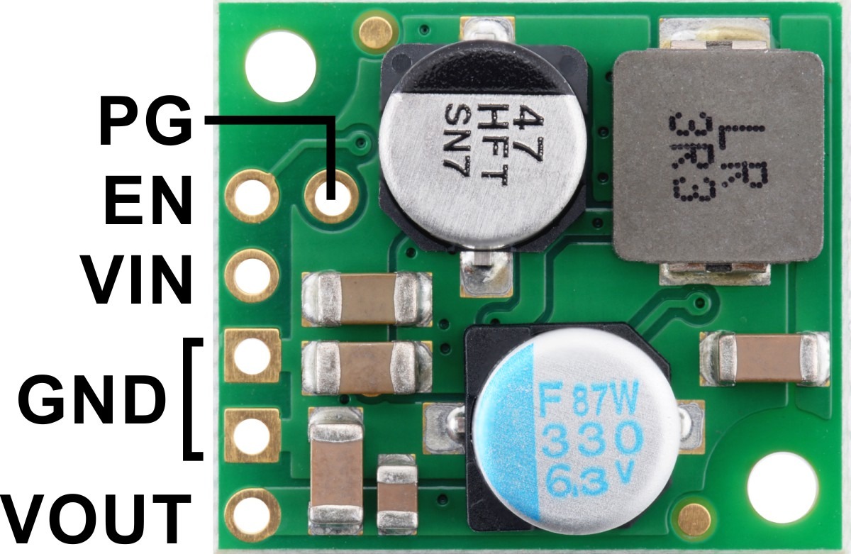
The module provides a power-good output that pulls low if output rises more than 20% above or falls more than 10% below nominal, and it needs an external pull-up. That signal can help a controller distinguish a supply fault from a software crash. The enable input turns the module off below 1.2 V and back on above 1.35 V, so a noisy or incorrectly biased enable line is another condition to check if both input headroom and thermal margin are adequate.
A decision based on loaded headroom
If the loaded input never stays above VOUT + Vdropout, improve the source path, raise the minimum source voltage or choose a buck-boost converter that can regulate when input approaches or crosses 5 V. If input headroom remains adequate while output fails, move to current-limit, thermal and stability checks. The simultaneous measurement is what separates those branches; replacing the converter before taking it only hides the evidence.