An ESP32 that appears to enter deep sleep and reboot immediately may be responding correctly to a wake source that is already active. Print esp_sleep_get_wakeup_cause() first; then inspect the configured EXT0 or EXT1 pin state before changing GPIO assignments or blaming the board.
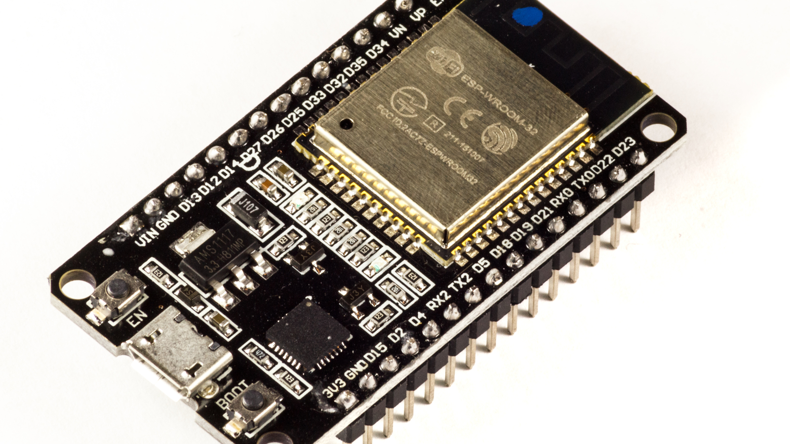
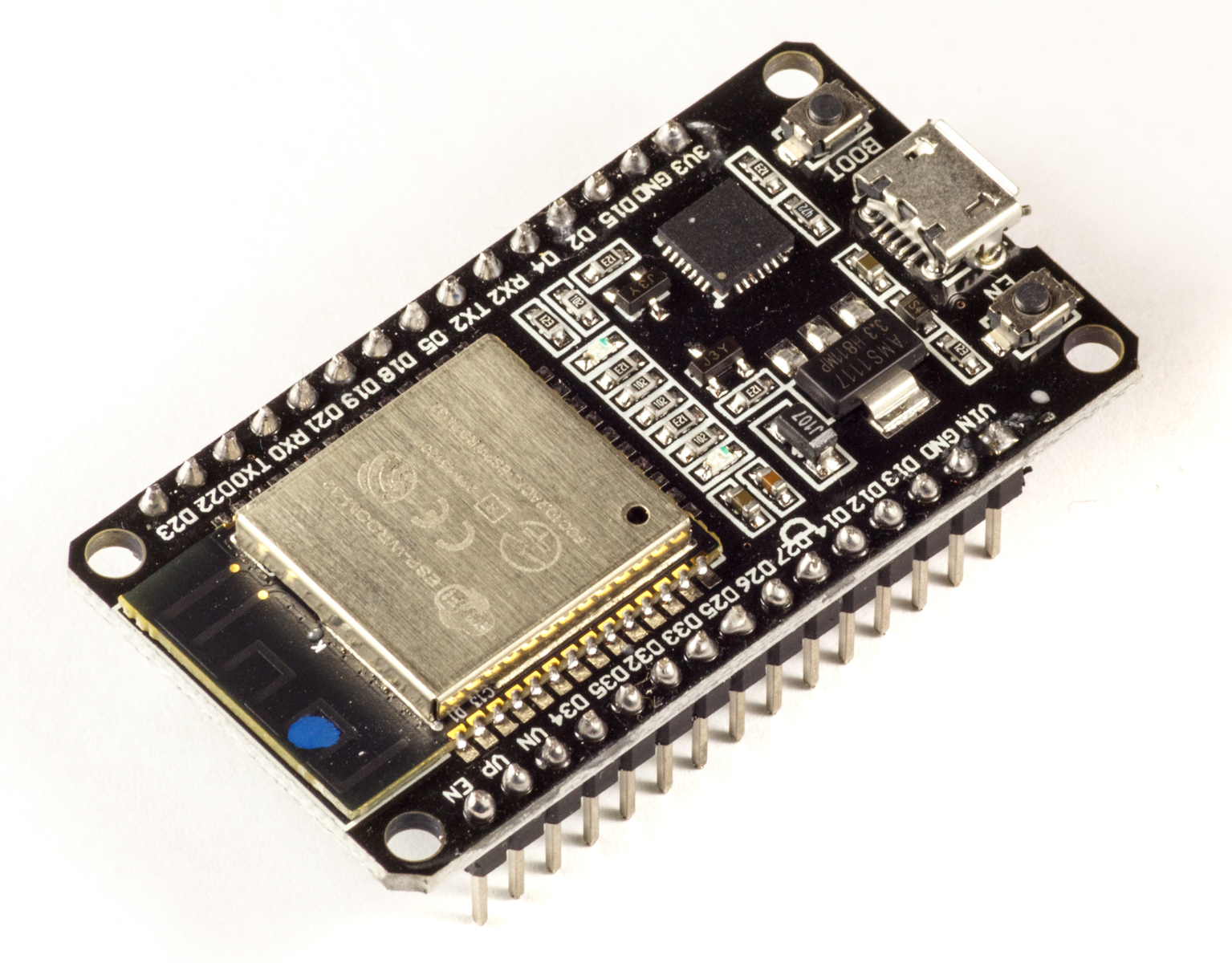
Featured image: Ubahnverleih/Wikimedia Commons, CC0. Cropped.
Espressif’s ESP32 sleep-mode documentation defines timer, touch, ULP and external GPIO wake sources. The immediate-wake symptom becomes tractable only after the firmware records which source actually fired.
Log the cause before re-entering sleep
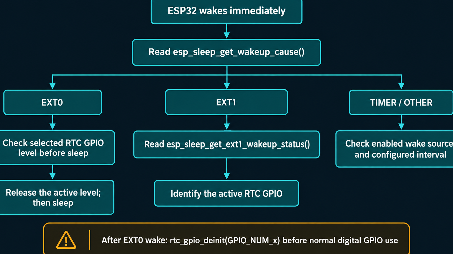
Call esp_sleep_get_wakeup_cause() during startup and print the returned enum before the program configures sleep again. A timer cause points toward an interval or unit error. ESP_SLEEP_WAKEUP_EXT0 or ESP_SLEEP_WAKEUP_EXT1 points toward an external level that satisfied the wake condition.
esp_sleep_wakeup_cause_t cause = esp_sleep_get_wakeup_cause();
Serial.printf("wake cause: %d
", cause);
The value is evidence, not the final diagnosis. A power-on reset and a wake from deep sleep do not have the same cause. Keep the log line early enough that a fast path does not return to sleep before serial output or retained telemetry captures it.
EXT0 is a level condition, not a remembered edge
On the classic ESP32, EXT0 uses one RTC GPIO and wakes when that input reaches the configured logic level. If a button is still held, a reed switch remains closed, or the circuit’s pull resistor leaves the pin at the active level, the chip can wake as soon as sleep begins. Waiting for the input to return inactive before calling esp_deep_sleep_start() prevents that loop.
Check the electrical state with the same polarity used in esp_sleep_enable_ext0_wakeup(gpio_num, level). An active-low button needs a stable pull-up and must read high before sleep; an active-high signal needs the corresponding inactive low state. Avoid a floating wake input. Espressif documents that EXT0 can use RTC-domain pull-up or pull-down controls because the RTC peripheral remains powered for this source.
EXT1 can identify the pin that fired
EXT1 evaluates multiple RTC GPIOs. On classic ESP32, the documented logic choices are any selected pin high or all selected pins low. After an EXT1 wake, esp_sleep_get_ext1_wakeup_status() returns a GPIO mask. Decode the set bit or bits instead of checking every input after other startup code has changed them.
If one pin repeatedly appears in the mask, measure its idle level at the board and at the external sensor. A pull resistor that is too weak for leakage, a sensor output that remains asserted, or a wiring inversion can all satisfy the condition without a new edge. The wake logic only sees the level it was configured to recognize.
Return EXT0 pads to digital GPIO mode after wake
Espressif warns that a pad used for EXT0 remains configured as RTC IO after wake. Before using it as ordinary digital GPIO, call rtc_gpio_deinit(gpio_num). Skipping that transition can make later reads or output configuration appear broken even though the wake event itself was valid.
That cleanup applies after wake; it does not fix an input that is already at its active level before sleep. The sequence is therefore: record the wake cause, decode the EXT1 mask when applicable, make the external condition inactive, deinitialize an EXT0 RTC pad before normal GPIO use, and only then arm the next sleep cycle.
Espressif’s Arduino-ESP32 DeepSleep examples separate timer, external and multi-source configurations. Use the example that matches the chip family and framework version; RTC-capable pins and supported wake logic differ across ESP32 variants. If the board fails before sleep rather than waking from it, TVG’s ESP32 GPIO0, EN and auto-reset diagnosis addresses that separate boot path.