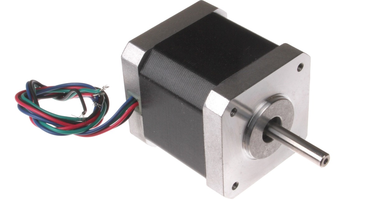
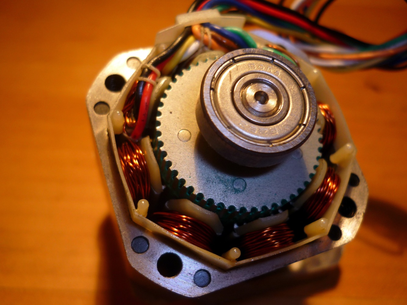
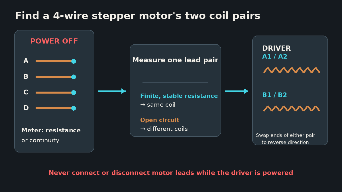
A four-wire bipolar stepper motor contains two electrically isolated windings. With power disconnected, the two leads from one winding show a finite, stable resistance to each other; a lead from one winding measured against a lead from the other reads open. That simple distinction identifies the pairs without trusting wire colors, which are not universal.
Featured image: oomlout/Wikimedia Commons (CC BY-SA 2.0; cropped).
Do not perform this check with the stepper driver energized. Pololu warns that connecting or disconnecting a motor while motor power is present can destroy the driver. Shut down the controller, remove its motor supply, and unplug the motor from the driver before using resistance or continuity mode.
Measure all six lead combinations
Label the unknown leads A, B, C and D with tape. Four leads create six unique two-lead combinations: AB, AC, AD, BC, BD and CD. A small table prevents a probe slip or repeated measurement from turning into a guessed result.
| Pair | Meter result | Interpretation |
|---|---|---|
| A–B | Record resistance or open | Finite resistance means one coil |
| A–C | Record resistance or open | Open means different coils |
| A–D | Record resistance or open | Continue until A’s partner is found |
| B–C, B–D, C–D | Confirm remaining possibilities | The unused two leads should form the second coil |
The exact resistance depends on the motor. The important pattern is two finite-resistance pairs with no continuity between the pairs. Very low winding resistance can resemble a meter-lead short on an autoranging display, so first touch the probes together and note the lead resistance. Subtracting that value is useful for comparison, but this procedure does not require a precision winding-resistance measurement.
Adafruit’s stepper-motor wiring guide documents the same identification rule: two wires that show a small resistance between them belong to one coil pair. That directly supports using resistance to separate the two windings before assigning the pairs to the driver outputs.
Map complete pairs to the driver
Once a pair is proven, connect its two ends to A1 and A2. Connect the remaining pair to B1 and B2. Pololu’s bipolar stepper instructions use exactly that topology: one coil on the A outputs and the other on the B outputs.
The order within each pair controls polarity, not pairing. If the motor turns opposite the desired direction, power down and swap the two leads of either complete pair. Swapping both pairs preserves the original direction. A direction pin or controller setting is usually a cleaner long-term solution, but the wiring rule helps distinguish a reversed axis from a mispaired motor.
A motor that locks, buzzes or rocks without rotating often has one driver phase connected to leads from different windings. The driver is changing current, but the stator field is not sequencing through the intended two coils. Return to the resistance table instead of trying random color orders. Also inspect terminals for a strand that is not actually clamped; an intermittent phase can mimic a wrong pair.
Four, six and eight leads are different cases
This method directly maps a four-lead motor because only the two winding ends are exposed. Oriental Motor’s wiring guide explains that a six-lead motor also exposes a center tap for each phase, while an eight-lead motor exposes both ends of two windings per phase. Those motors can support unipolar, bipolar-series, bipolar-parallel or half-coil arrangements depending on lead count and driver.
On a six-lead motor, a center tap measures approximately half the end-to-end resistance to either end of the same phase. An eight-lead motor requires identifying four individual windings and then using manufacturer documentation to establish polarity before series or parallel connection. Treating either case as a simple four-wire motor can produce the wrong current and inductance behavior.
Pairing does not set the safe current
Correct coil pairs only establish topology. They do not tell the driver how much current the motor can tolerate. Pololu defines the motor’s rated current as the maximum intended current per phase and gives the winding relationship V = I × R for rated voltage, current and coil resistance. Chopper drivers commonly run from a supply voltage above the winding’s rated voltage while actively limiting phase current.
After identifying the windings, use the motor’s datasheet current rating and the driver’s documented adjustment method. TVG’s guide to set a DRV8825 phase-current limit from VREF explains why bench-supply current is not a substitute for phase-current configuration. If the motor has no trustworthy label or datasheet, begin conservatively and establish a thermal limit rather than assuming that wire gauge or NEMA frame size defines the rating.
The stopping point is equally clear: if the six measurements do not resolve into two isolated finite-resistance pairs, the cable, connector or winding may be damaged—or the motor may not be the four-wire bipolar type assumed. Do not connect it to a powered driver until the topology is resolved.