If an HX711 scale reads the calibration mass correctly but changes when the same object moves across the platform, the factor is not the first problem. Fix the force path, wiring and warm-up behavior before tuning software. Calibration should convert repeatable raw counts into units—not hide a mechanical fault.
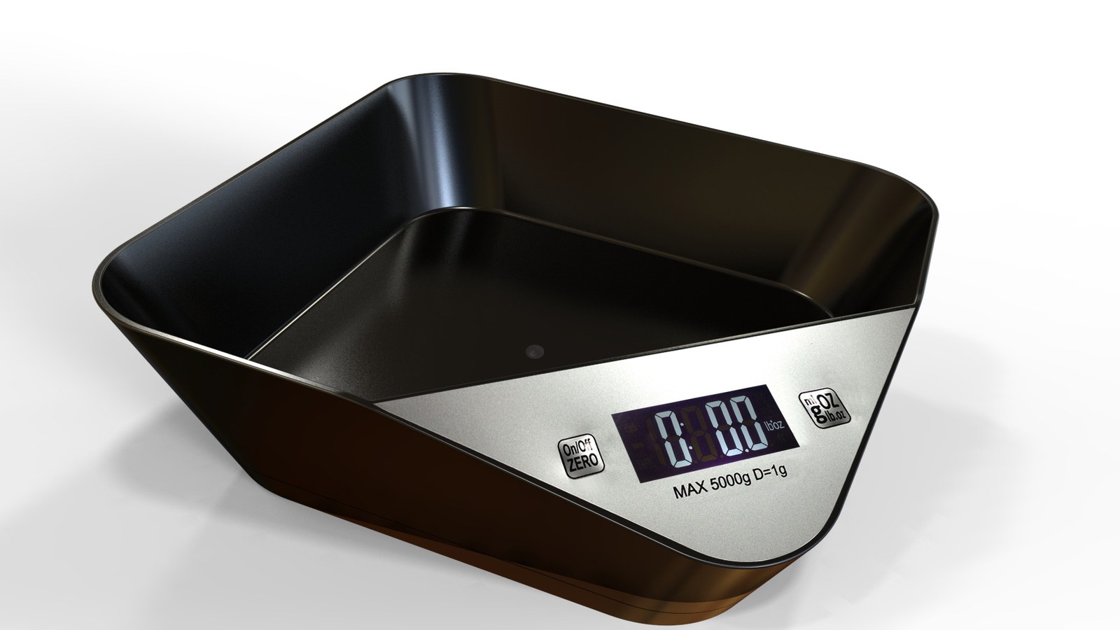
Featured image: Lifedics/Wikimedia Commons (CC BY-SA 3.0; cropped to 16:9).
Make the load path repeatable
A bar load cell normally mounts between two plates with one end fixed to the base and the opposite end supporting the platform. Leave the strained section free to bend. If both ends are clamped to both plates, a cable pulls on the platform, or the plate touches the enclosure, the force can bypass the intended flexure.
Press the same known mass at the center and near each corner. Large position-dependent changes point to platform flex, contact with the enclosure, unequal feet or a poorly centered button sensor. A software multiplier cannot correct a geometry that changes with load position.
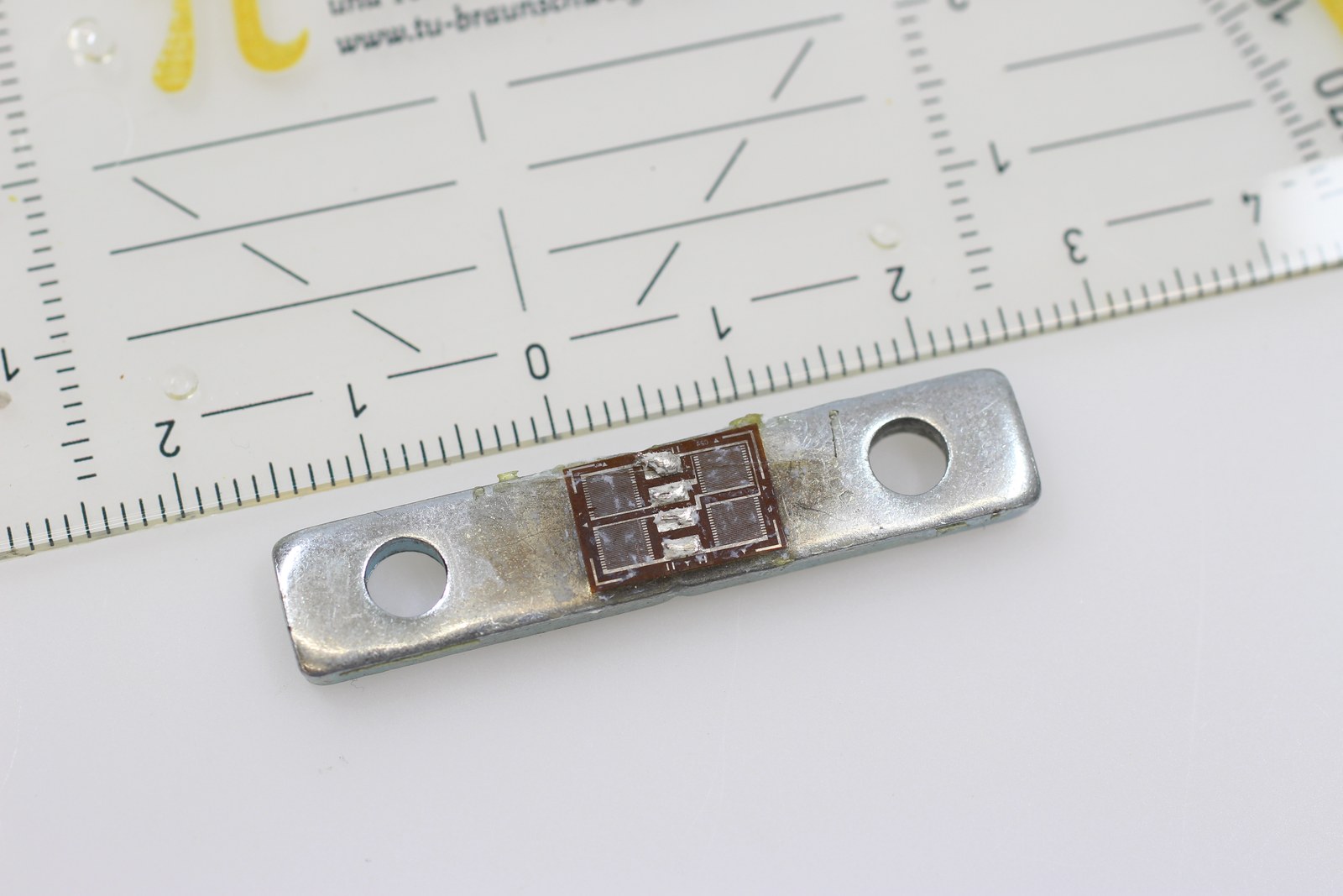
Source and license: Make Magazin DE/Wikimedia Commons · CC BY-SA 4.0 (resized without cropping).
Confirm the bridge and supply before calculating a factor
Do not trust wire colors without the load-cell datasheet. Typical four-wire bridges expose excitation positive and negative plus signal positive and negative, but conventions vary. If adding weight makes raw counts decrease, swapping the signal pair changes the sign; using a negative factor is also valid when the wiring is otherwise correct.
The HX711 supports separate analog and digital supplies in some breakout designs. Its datasheet lists a 2.6–5.5 V operating range, selectable gains of 32, 64 and 128, and 10 or 80 samples per second. Record the board’s supply, gain and rate with the calibration value. A factor produced under one configuration is not a portable constant for every module and load cell.
Calculate from zero and a known mass
Warm the electronics long enough for the zero reading to settle, unload the platform and average a baseline. Place a known mass that is large enough to produce a clear span but remains comfortably below the cell’s rated capacity. Then use:
calibration_factor = (loaded_raw - zero_raw) / known_massFor example, if the unloaded average is 84,200 counts and a 2.000 kg mass produces 1,284,200 counts, the factor is 600,000 counts/kg. The application reading becomes:
mass = (raw - zero_raw) / calibration_factorThe sign may be negative. What matters is that the factor, zero offset, units, sample rate and gain stay together. The commonly used bogde HX711 library follows this sequence: call set_scale() without a factor, tare(), place a known mass, read the result, divide by the mass and then apply that factor with set_scale(factor).
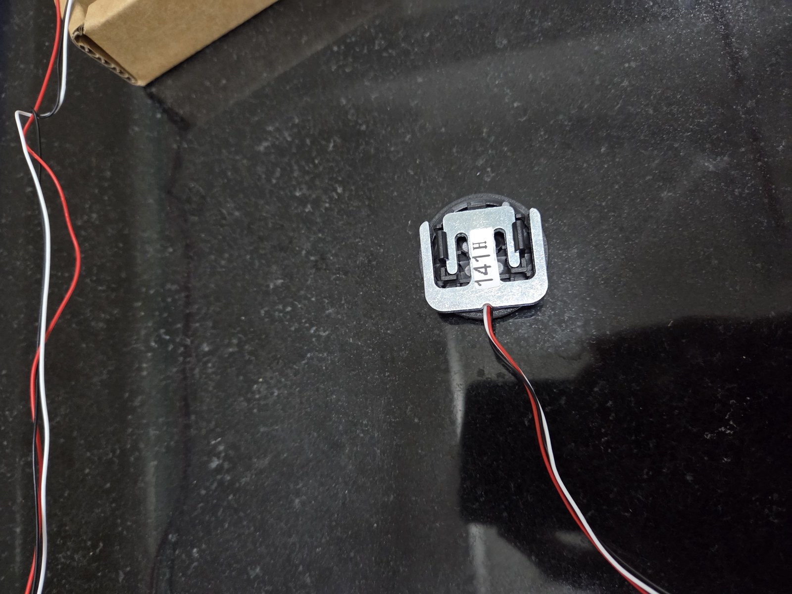
Source and license: Gannu03/Wikimedia Commons · CC BY-SA 4.0 (resized without cropping).
Use two checks that a single calibration point cannot pass by accident
First, remove and replace the calibration mass several times. The reading should return close to zero when unloaded and close to the same value when loaded. Second, check at least one different mass, preferably in another part of the intended range. If the calibration point is correct but the second point is not, look for overload, mechanical contact, nonlinearity or an incorrect known mass.
Then move the same mass across the platform. A four-sensor scale depends on equal geometry and a correctly wired bridge; a single bar cell depends on a rigid platform and correct mounting. Position sensitivity is a mechanical diagnostic, not a reason to create separate calibration factors for each corner.
Separate noise, creep and thermal drift
Short-term jitter can often be reduced by averaging multiple samples. At 10 samples per second, an average of ten new readings represents roughly one second of data; at 80 samples per second it covers roughly 0.125 seconds. Those windows do not have the same noise rejection or response time, so record the output rate when comparing results.
Creep is different: under a constant load, the reading slowly moves as the mechanical system settles. Temperature can shift the bridge, amplifier and structure even with no load change. SparkFun notes that temperature, creep, vibration, drift and electrical or mechanical interference can push maker load-cell measurements by about ±5%. More averaging can make a drifting number look smooth without making it correct.
Log three traces separately: unloaded zero versus time, a fixed mass versus time, and repeated load/unload cycles. Zero movement implicates thermal or electrical offset; movement only under load suggests creep or mounting; random fast variation suggests vibration, supply noise or EMI. Keep load-cell leads away from motors and switching nodes, preserve any shield connection recommended by the module maker, and add strain relief so the cable cannot apply force to the cell.
Store calibration as configuration, not a magic number
Save the factor with units, zero method, gain, output rate, load-cell identity and calibration date. Validate the stored value before use and provide a deliberate recalibration path. If the platform, fasteners or sensor changes, create a new record rather than carrying the old factor forward.
The useful finish line is repeatability: the same mass, position and conditions produce the same result within the tolerance the project actually needs. For dimensional checks where force is not the measurement, see TVG’s guide to choosing a digital caliper or micrometer for 3D-printed parts.