If an I²C scan returns no devices and one bus line sits near 0 V, stop changing addresses. A bus that is stuck low is an electrical or protocol-state fault. Check SDA and SCL at idle, identify which line is being held down, then recover or isolate the bus in a deliberate order.
Featured image: Sumanch/Wikimedia Commons (CC BY-SA 3.0; cropped to 16:9).
First measurement: which line is low?
With the controller idle, both SDA and SCL should be released and pulled high. Measure each line against the bus ground with a multimeter; if available, confirm the transition shape with an oscilloscope or logic analyzer. Record the bus supply, because a “high” level must be interpreted against the logic voltage rather than assumed to be 5 V.
If SDA is low while SCL is high, a target may be waiting to finish transmitting a byte after the controller reset midway through a read. If SCL is low, a target may be stretching the clock, the controller pin may be misconfigured, or there may be a short. If both rise but do so slowly, the failure belongs to capacitance and pull-up sizing rather than bus recovery.
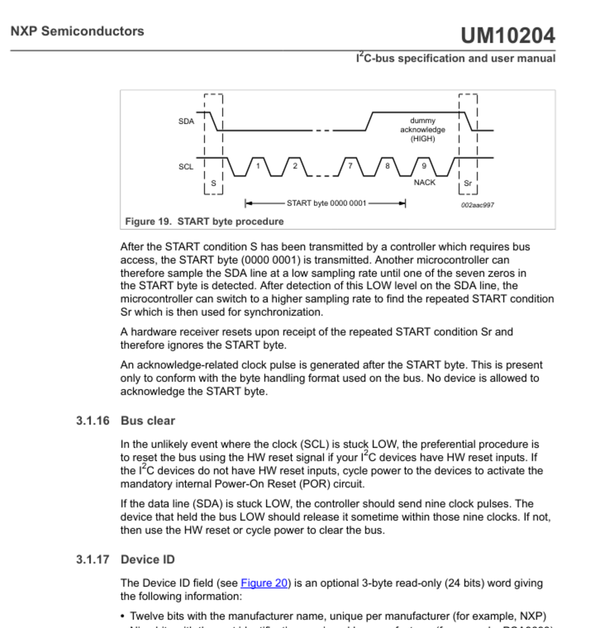
Recover SDA with clocks, not a blind reboot loop
NXP’s I²C manual describes a recovery sequence for the common case where a target remains in transmitter mode: send nine clock pulses on SCL, keep SDA high through the acknowledgement position, and let the target return to idle. A robust implementation then issues a STOP by allowing SDA to transition low-to-high while SCL is high, provided the bus has actually been released.
The number nine is tied to the byte protocol. Each transferred byte has eight data bits followed by a ninth acknowledgement clock. Clocking through that boundary gives a target that lost controller state a chance to finish the pending byte. It is not a magic reset for damaged hardware.
release(SDA);                 // input/open-drain high
for (int i = 0; i < 9 && !read(SDA); ++i) {
    drive_low(SCL);
    delay_us(t_low);
    release(SCL);
    wait_until_high_or_timeout();
    delay_us(t_high);
}
if (read(SCL) && read(SDA)) generate_stop();
else isolate_or_reset_target();
Choose delays that respect the slowest device and bus mode. NXP specifies minimum SCL low/high periods of 4.7/4.0 µs for Standard-mode and 1.3/0.6 µs for Fast-mode. A recovery routine should also time out while waiting for SCL to rise; otherwise one stuck line can hang startup forever.
When nine clocks do nothing
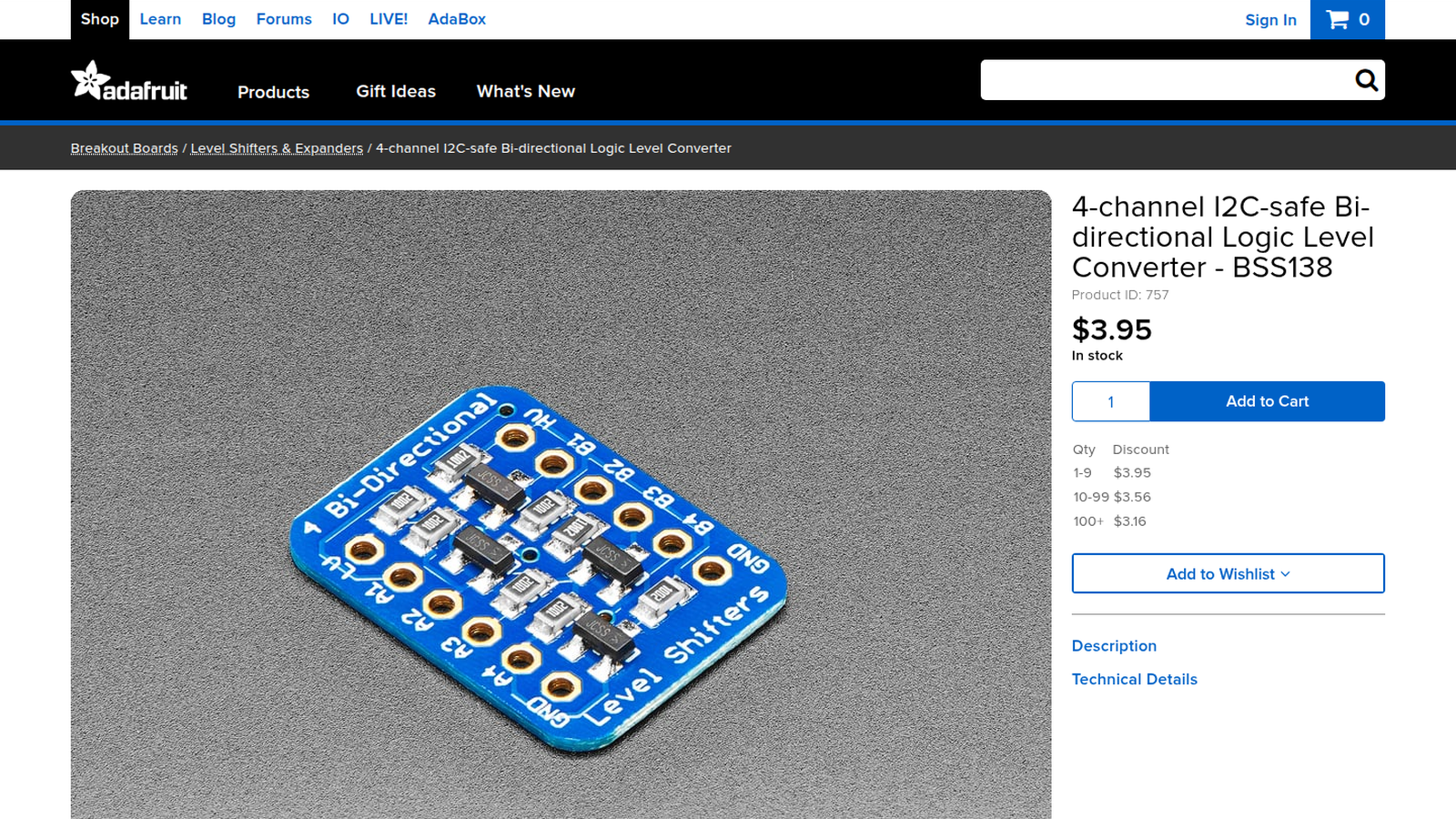
If SDA remains low after the pulses, power down and isolate branches. Disconnect one target or cable segment at a time, then recheck the idle voltage. A bus buffer, level shifter or mux creates an obvious boundary: test on both sides. This is faster than swapping pull-ups because it answers whether the low is local to a device, a branch or the controller board.
For SCL stuck low, inspect the controller’s pin mode before blaming a target. I²C outputs are open-drain; firmware releases a line rather than driving it high. A pin accidentally configured as push-pull low looks exactly like a bus fault. Then check for a target performing clock stretching, an unpowered device clamping through an I/O protection path, solder bridges and connector pin swaps.
Slow rise time is a different failure
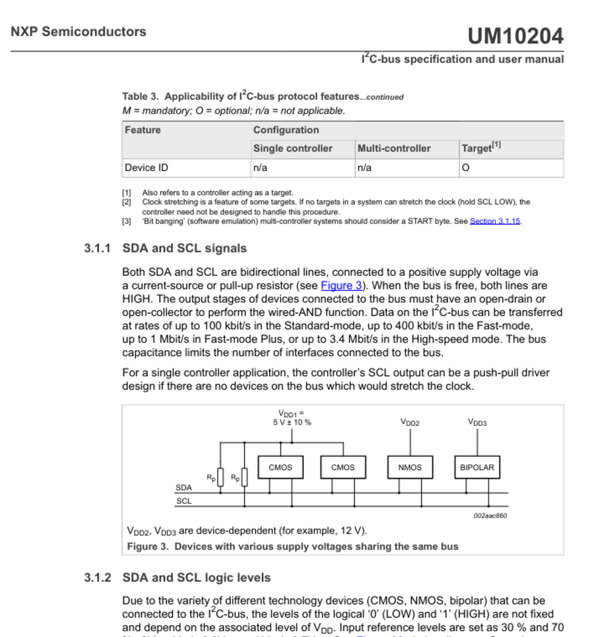
An analyzer may decode intermittent NACKs even though neither line stays low. In that case, measure the rising edge. The bus is an RC network: lower pull-up resistance accelerates the rise but increases sink current. NXP’s specification allows different maximum rise times by mode, and a design that works at 100 kHz may fail at 400 kHz when cable or device capacitance increases.
Use the measured rise time to choose the resistor rather than treating a smaller value as a universal cure. TVG’s I²C pull-up resistor guide covers that calculation. Recovery pulses address state loss; pull-up changes address edge rate.
Make recovery observable in firmware
Run the bus check before the first transaction and after a transfer timeout. Log SDA/SCL levels before recovery, the number of pulses sent, whether SCL actually rose, and which reset or power-control action followed. Cap the retry count so a failed sensor cannot consume the entire boot sequence.
The Linux kernel’s I²C fault-injection documentation makes the same distinction explicit: it can simulate an incomplete transfer, force SCL low or force SDA low. Its SDA-low case notes that recovery cannot succeed while the injector physically pins the line low. That is the useful boundary for maker firmware too: clocks can repair protocol state, not a hard electrical assertion.
A stable fix leaves evidence. If nine pulses repeatedly recover one sensor after brownouts, investigate its reset and power sequencing. If removing one branch immediately releases SDA, inspect that branch’s target and level shifting. If the lines are high but edges violate timing, return to capacitance and pull-ups. Each symptom has a different repair.