When a UART decoder produces random bytes, the fastest recovery is to measure one bit on the wire instead of cycling through baud-rate presets. Capture the idle level and several frames, measure the shortest repeated pulse that represents one bit, then calculate baud ≈ 1 / bit_time. Only after that should you resolve inversion, data bits, parity and stop bits.
Featured image: Shelby Jueden/Wikimedia Commons (CC BY-SA 4.0, cropped).
Prove the electrical signal before decoding it
Connect analyzer ground to the target ground and probe the transmitter’s TX line at logic level. Do not connect a typical low-voltage logic analyzer directly to RS-232 voltage levels; use the signal on the UART side of the line driver or a properly rated interface. An idle UART is normally high and a frame begins with a low start bit, but inverted signaling exists.
Choose a sample rate that places several samples inside each bit. Ten samples per bit is a practical starting point for inspection: 115,200 bit/s needs at least about 1.152 MS/s, while a 24 MS/s analyzer provides roughly 208 samples per bit. More samples improve edge placement, but they do not correct ground, threshold or level-shifting errors.
Measure the shortest clean bit interval
Saleae’s async-serial guide recommends measuring two adjacent bits of opposite state and taking the inverse of the interval between transitions. A 104.17-microsecond bit corresponds to about 9,600 bit/s; 8.68 microseconds corresponds to about 115,200 bit/s. Long high or low runs are multiples of the bit period, so use the greatest common interval visible across several frames rather than assuming every pulse is one bit.
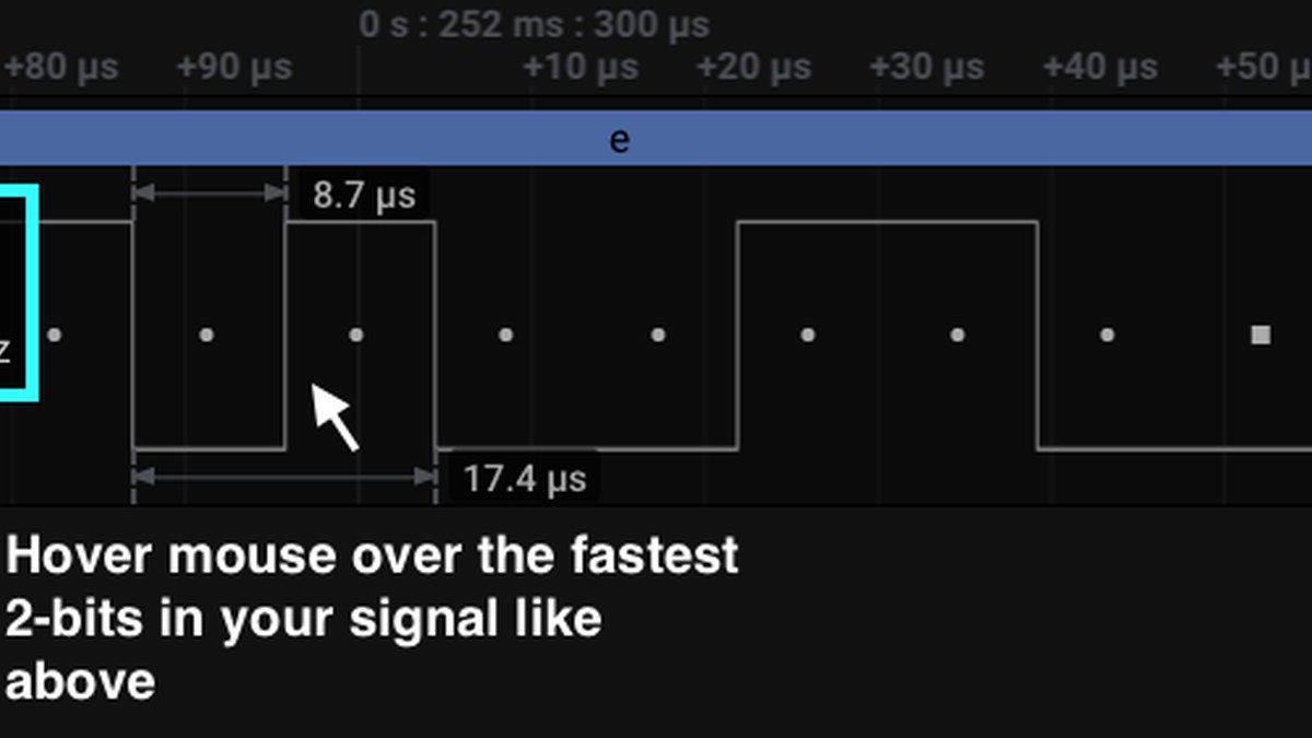
Auto-baud estimates need the same caution. Saleae says its estimator tracks the narrowest pulse and assumes it is one bit. It will fail when that pulse is only one sample wide, and it leaves the entered rate unchanged when the estimate is within 5%. Noise spikes can therefore look like impossibly fast bits; zoom in and reject pulses that do not repeat at frame-consistent boundaries.
Resolve framing in a fixed order
Set the measured baud, then start with the common 8-N-1 frame: eight data bits, no parity and one stop bit. If every frame begins on the expected falling edge but decoded bytes remain wrong, check whether RX is inverted. The sigrok UART decoder exposes invert_rx, num_data_bits, parity_type, num_stop_bits and bit_order as separate options, which makes each assumption visible.
Framing errors at the end of otherwise recognizable bytes point toward the stop-bit, parity or rate choice. A consistently shifted decode can indicate the wrong edge polarity or a measurement made on the opposite side of an inverting transceiver. Random changes in bit width point back to signal integrity, threshold or clock stability rather than text encoding.
Validate with a known repeating byte
A repeating 0x55 pattern is especially useful because its alternating bits create frequent transitions. If firmware access exists, transmitting that byte makes the bit period easy to measure. Without firmware control, capture enough traffic to find repeated headers and confirm that the decoded values remain stable across more than one frame.
Do not call the result solved because one word looks readable. Record sample rate, voltage threshold, idle polarity, measured bit time, selected baud and frame format. That small evidence set distinguishes a true UART configuration from a coincidental decode and complements TVG’s guide to stable Linux USB serial device names once the physical link itself is understood.