An oscilloscope can display a clean-looking waveform that did not exist until the probe touched the circuit. On fast digital edges and low-impedance power rails, a passive probe’s input capacitance and ground-loop inductance can round an edge, shift phase or create ringing. The first troubleshooting step is therefore to qualify the probe connection before blaming the board.
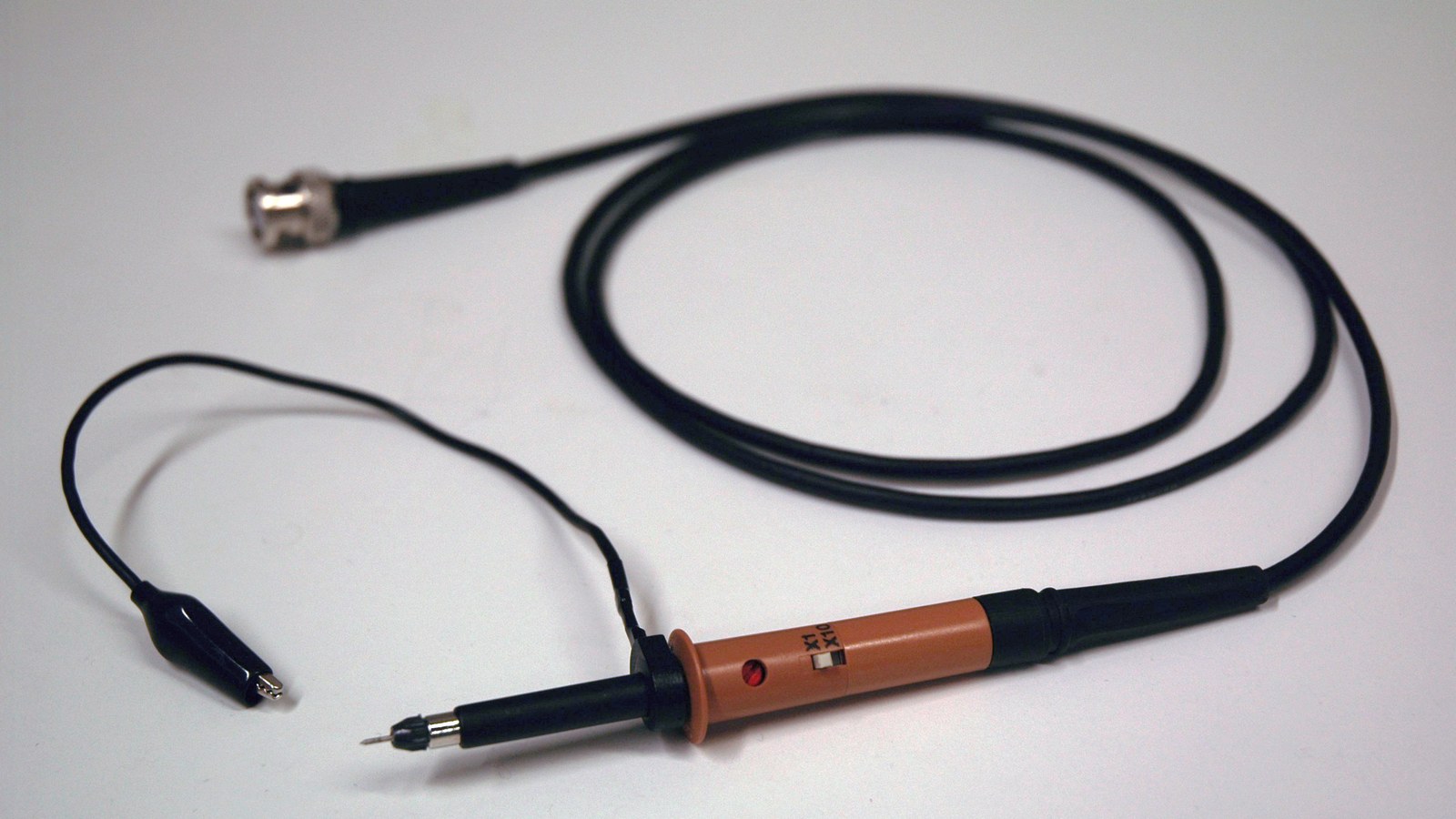
Featured image: Nuno Nogueira/Wikimedia Commons (CC BY-SA 2.5; cropped to 16:9).
Start with the load, not the scope’s bandwidth number
A typical 10× passive probe may be labeled 10 MΩ, but that resistance describes only the low-frequency part of its input. Tektronix notes that resistance, capacitance and inductance all load the test point. Teledyne LeCroy gives a concrete example: its discussed 10× probe has 9.5 pF input capacitance, whose reactance falls to about 250 Ω at 100 MHz. A high-impedance label does not make that capacitance disappear.
The first-order capacitive reactance is:
|Xc| = 1 / (2πfC)As frequency rises, |Xc| falls. That can slow a rising edge or alter a high-impedance node even when the measured fundamental is modest. Tektronix’s application note demonstrates the effect by adding 50 pF to a test point: the loaded waveform develops a slower front edge and a phase shift.
Source and license: Ge²/Wikimedia Commons · CC BY-SA 3.0 (cropped to 16:9).
Compensate every 10× probe on the channel you will use
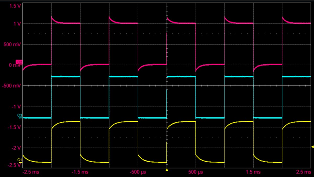
A 10× probe and scope input form a compensated divider. Cable and input capacitance vary enough that moving the probe to another channel or instrument can upset the match. Connect the probe to the oscilloscope’s square-wave calibration output, select the same attenuation factor in the channel menu, and adjust the probe’s compensation trimmer until the square-wave top is flat.
Under-compensation produces a rounded rise toward the flat top. Over-compensation produces a peaked or overshooting corner. A correctly compensated probe produces the flattest available square wave. Pico Technology describes low-frequency and high-frequency adjustments on probes that provide both; many basic probes expose only the low-frequency trimmer. Do not use the trimmer to “fix” ringing seen only on the circuit under test—first verify the calibration waveform.
Shorten the return path before interpreting ringing
The long alligator ground lead supplied with many probes creates a loop with the probe tip. Teledyne LeCroy estimates about 85 nH for a one-inch-diameter circular loop and says practical tip-loop inductance can reach 200 nH. Combined with probe input capacitance, that inductance forms an LC resonance. In its example, a 200 nH loop and 9.5 pF input on a low-resistance 5 V rail produced observed ringing near 80 MHz, close to a modeled peak around 100 MHz.
Replace the long ground lead with the probe’s ground spring or another very short return connection, touching signal and ground points that are physically adjacent. If the ringing frequency or amplitude changes substantially, the connection is part of the measurement. A differential probe is appropriate when neither point can be safely tied to the bench scope’s earth-referenced ground; it is not permission to exceed the probe’s common-mode or differential-voltage rating.
Check whether the probe-scope pair is fast enough
Bandwidths in a cascaded measurement chain do not simply equal the lowest headline number. For approximately Gaussian responses, a practical estimate is:
tr(system) ≈ √(tr(scope)² + tr(probe)²)
tr ≈ 0.35 / bandwidth
A nominal 100 MHz measurement path corresponds to roughly 3.5 ns rise time under that approximation. A 1 ns edge contains energy well beyond 100 MHz, so a 100 MHz probe-scope pair will report a slower transition even when it is perfectly compensated. Use the signal’s edge rate—not only its clock frequency—to choose bandwidth.
A four-observation fault check
- Record probe attenuation, input capacitance and rated bandwidth.
- Capture the calibration square wave before and after adjustment.
- Capture the DUT with the long ground lead, then with a spring ground at the same point.
- Repeat at a slower timebase and, where safe, with a second probe or channel to separate repeatable circuit behavior from connection artifacts.
This is a measurement-validity check, not a substitute for electrical safety. Bench oscilloscope ground clips are commonly earth referenced. Never attach one to a live mains-referenced node unless the complete instrument and probe arrangement is designed and rated for that measurement. For a related signal-integrity example after the probe is qualified, TVG’s robot sensor power-rail noise guide separates grounding, decoupling and filtering symptoms.