An SPI decoder can print plausible bytes even when the capture is wrong. Before debugging firmware, prove four boundaries in order: the physical connection, the digital threshold, the sample rate, and the decoder’s SPI mode. Each boundary produces a different kind of false result.
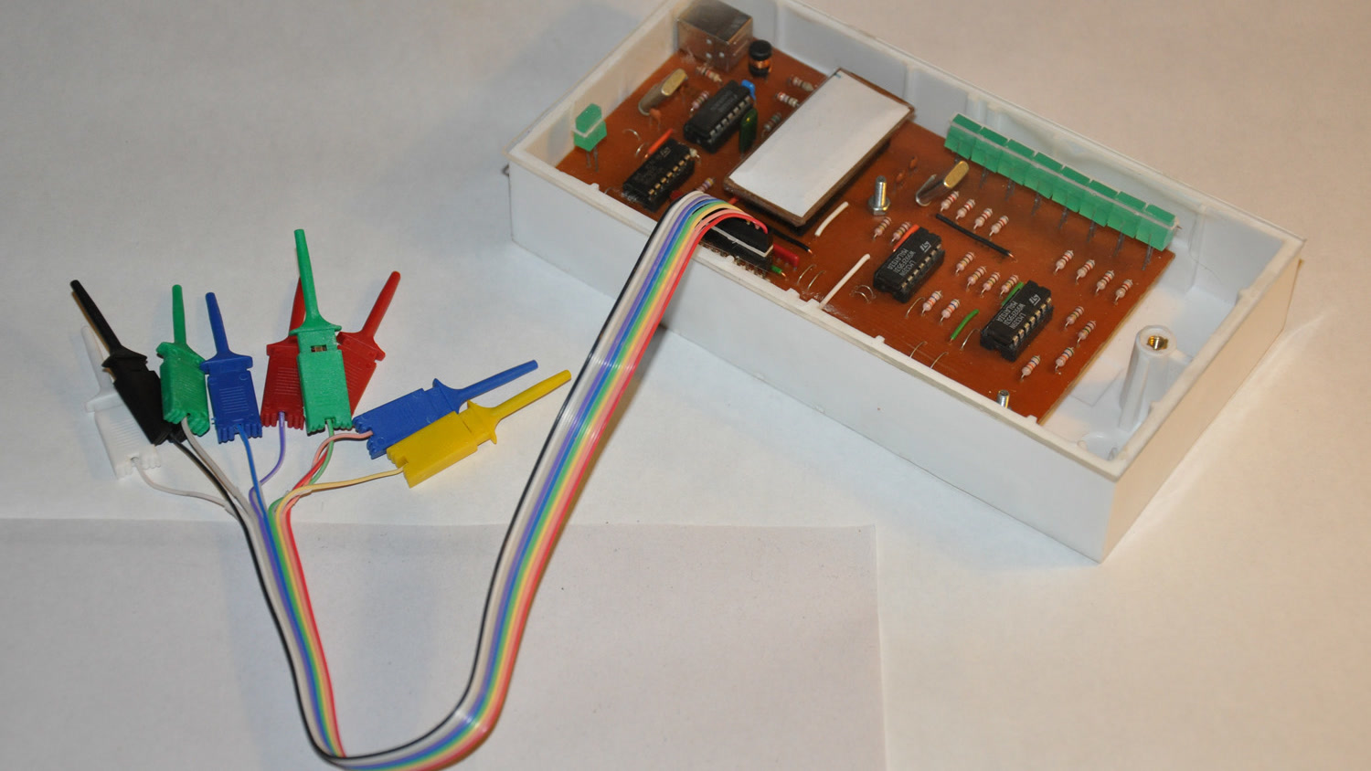
Featured image: Dilshan Jayakody/Wikimedia Commons (CC BY-SA 2.0; cropped to 16:9).
Start with the electrical reference
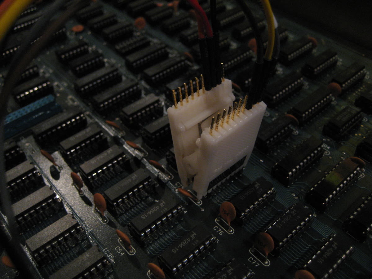
Connect the analyzer ground to the device ground before interpreting clock or data. Then identify the exact signals: clock, chip select, controller-out/peripheral-in, and peripheral-out/controller-in. A swapped data pair can look like an idle channel rather than a dramatic failure.
Check that the analyzer can safely accept the signal voltage and that its threshold matches the logic family. Saleae documents selectable thresholds on Logic Pro models; its 3.3+ V setting uses a 1.65 V threshold, while other models may use fixed thresholds. A threshold that sits too close to a noisy edge can create extra transitions or miss real ones.
Give the capture enough samples
Saleae recommends a digital sampling rate at least four times faster than the recorded signal’s bandwidth. Treat that as a floor, not a guarantee of comfortable timing detail. A common low-cost analyzer documented by SparkFun captures at up to 24 MHz; at a 6 MHz SPI clock, that is exactly four samples per clock period.
Four samples can show whether transitions exist, but it leaves little room for clock jitter, narrow chip-select timing, or edge-placement questions. If a 24 MHz device produces unstable decoding at 6 MHz SPI, lowering the bus clock to 3 MHz doubles the nominal samples per period from four to eight. That controlled change separates a capture-resolution limit from a firmware data-format problem.
Do not apply the four-times figure blindly to every signal description. The relevant constraint is the fastest digital behavior the analyzer must preserve, including narrow pulses and data edges, not only the transaction rate printed on a product page.
Match the decoder to the wire protocol
SPI does not encode its mode on the wire. The decoder needs the correct clock polarity and phase, commonly represented as modes 0 through 3. It also needs the correct bit order, bits per transfer, and chip-select behavior. A one-edge phase error can shift every word while still producing a neat stream of hex values.
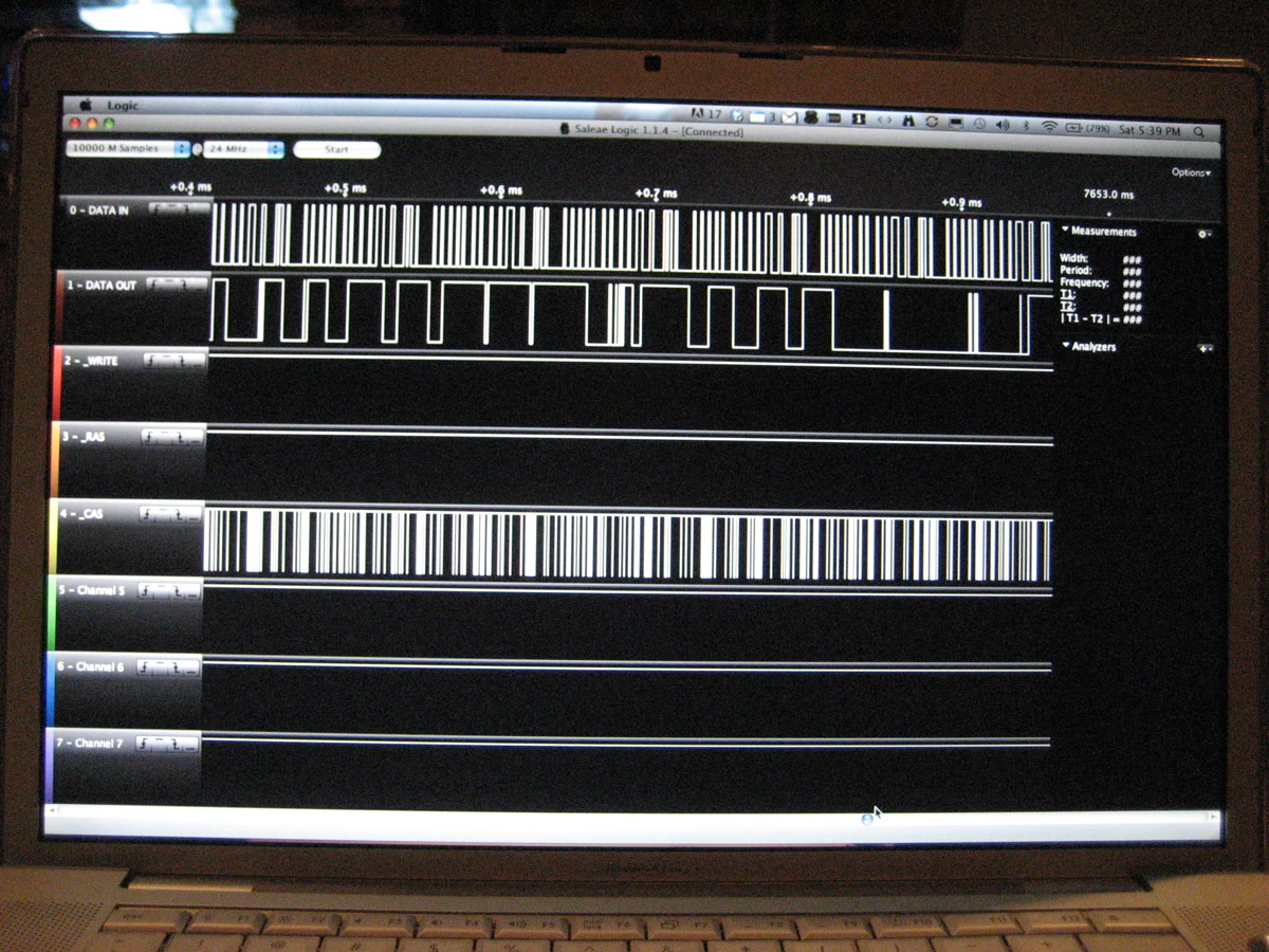
Use the waveform before trusting the annotation. Confirm the idle clock level, note which edge changes data, and inspect which edge samples stable data. Then set polarity and phase to match that observed relationship and the peripheral data sheet. If chip select frames 16 clock pulses but the decoder expects 8-bit transfers, decide whether the protocol is two bytes or one 16-bit word before interpreting values.
Use a short capture that contains a known event
Capture one repeatable transaction: a device-ID read, a fixed register write, or another operation whose command structure is documented. Trigger on chip select if the software and analyzer support it. A short known exchange is easier to inspect than minutes of traffic, and it gives a direct check on word boundaries.
PulseView’s workflow separates captured channels from protocol decoders, so changing decoder settings does not repair a bad electrical capture. Conversely, a clean clock and data waveform can be decoded several ways. Save the raw capture before changing mode, word size, or bit order so the interpretation remains reproducible.
A symptom-to-boundary map
- No activity on every channel: check ground, probe location, channel enablement, and trigger conditions.
- Edges appear but timing is coarse: raise the sample rate or lower the SPI clock.
- Waveforms look clean but bytes are shifted: verify polarity, phase, bit order, transfer width, and chip-select framing.
- Extra edges appear near transitions: check threshold selection, wiring length, ground quality, and whether an oscilloscope is needed to see analog integrity.
- Only one data direction is empty: confirm the probe is on the expected controller-to-peripheral or peripheral-to-controller line.
A logic analyzer is strongest when it answers a bounded digital question. It can show sampled highs and lows, timing relationships, and decoded transactions. It cannot by itself show ringing, marginal voltage levels, or rise-time detail hidden between samples. When the digital capture changes with probe placement or threshold, move the electrical-integrity question to an oscilloscope.