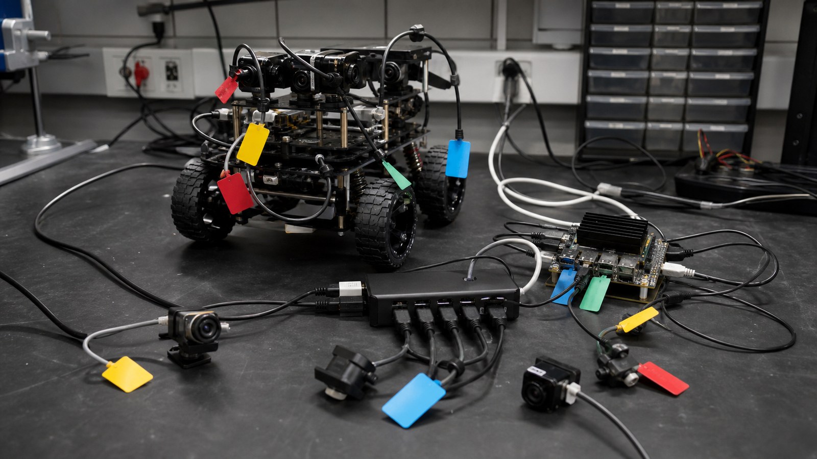
Robot camera cable labels are cheap insurance against losing hours to swapped USB, CSI, Ethernet, trigger, or power leads during field debugging.
That sounds too basic for a machine-vision problem, but it is one of the cheapest reliability fixes in a student robotics lab, maker space, or small automation shop. Label the camera cable, port, power path, and test configuration before the next demo, and many “software” failures become easier to reproduce.
Quick answer
Label robot camera cables by camera role, port, direction, length, power source, and known-good test date. Pair labels with a simple port map and strain-relief check so camera swaps do not create hidden configuration changes.
Why labels matter in vision debugging
Vision systems are sensitive to small changes. A cable swap can change bandwidth, power stability, connector fit, hub behavior, or camera enumeration order. A camera that appears as one device path in a test session may appear differently after a reboot or port change.
Robotics software stacks such as ROS can handle complex camera pipelines, but they still depend on the physical system being understandable. If the left camera, front depth camera, and inspection camera all use similar black cables with no labels, the lab has created an avoidable failure mode.
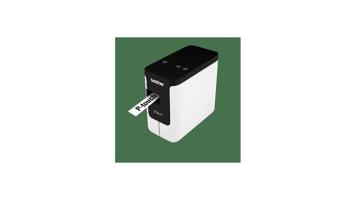
Minimum label set
- Camera role: front navigation, arm inspection, AprilTag, driver view, overhead test camera.
- Connector and bus: USB, MIPI CSI ribbon, Ethernet/PoE, HDMI capture, or adapter chain.
- Port destination: hub port, compute-module port, switch port, or camera adapter board.
- Power source: bus-powered, PoE, separate regulator, or shared accessory rail.
- Known-good date: last date the camera was tested with the current cable and software image.
This support article strengthens TVG’s robot-camera cluster, including field-of-view calibration, robot-camera lighting, and lens cleaning and focus checks.
How to make the labels useful
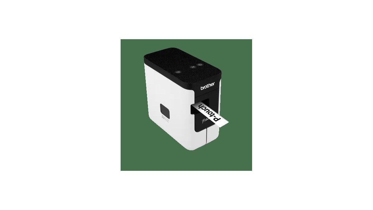
Good labels use short codes that match a setup note, not tiny essays wrapped around a cable. For example, a front camera might be marked FC-USB-A2, meaning front camera, USB, port A2. A PoE inspection camera might be marked IC-POE-3, matching switch port 3. The note can then list resolution, frame rate, driver package, and the last known-good test image.
Take a phone photo of the working wiring state before changing anything. That image becomes a fast rollback reference when a student, teammate, or technician has to rebuild the robot after transport.
Do not skip strain relief
A perfect label does not fix a cable that is bent against a sharp bracket. Camera cables should have enough slack for expected motion, a controlled bend radius, and a tie-down point that does not pull directly on the connector. Ribbon cables need especially careful routing because they can loosen or crease during chassis work.
When labels expose the real bug
Once the cable path is labeled, teams often discover that the same camera fails only on one hub, only with one long cable, or only when another device is active. That narrows the investigation from “vision is broken” to power drop, bandwidth sharing, connector damage, or device-order configuration. The label is not the fix by itself; it is what makes the fix testable.
For competition teams, the value is even clearer after transport. A robot unloaded from a case should not depend on memory to decide which camera cable goes where.
TVG Take
Robot vision reliability is not only model accuracy. It is the whole signal path from lens to cable to port to software node. Labeling will not make a bad camera good, but it will make failures easier to isolate and fixes easier to repeat. The same habit also helps new team members learn the system without inheriting every undocumented wiring choice from the last build session.