
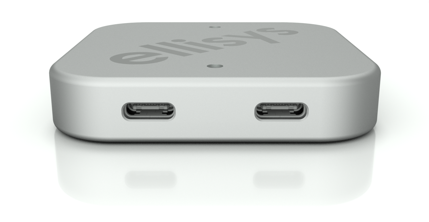
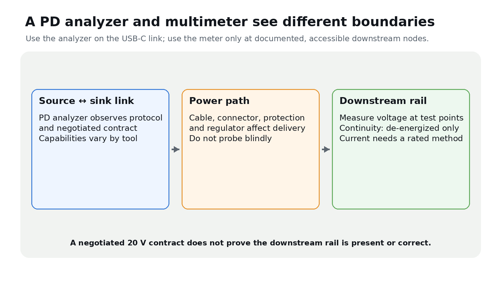
Fault-isolation rule: A USB-C PD analyzer and a multimeter answer questions at different electrical boundaries. The analyzer observes the source–sink link and negotiated power contract. The meter measures voltage, resistance, continuity or current at an accessible circuit node. Neither reading automatically proves what the other boundary is doing.
Start with the PD contract
In USB Power Delivery, a source advertises capabilities and a sink requests an available option. After acceptance, the link operates under that contract. A capable analyzer can display voltage/current terms and, depending on the instrument, decode PD messages. Verify exactly which PD revision, EPR modes, cable markers and message types the tool supports.
USB PD Extended Power Range can deliver up to 240 W, but only in a compliant source, sink and cable system. A USB-C connector or a “240 W” cable does not make an unsupported charger or load use EPR.
Standard fixed supply voltages are 5, 9, 15 and 20 V in SPR, with 28, 36 and 48 V added for EPR. Adjustable modes require compatible endpoints and an analyzer that can decode them.
Then measure the downstream result
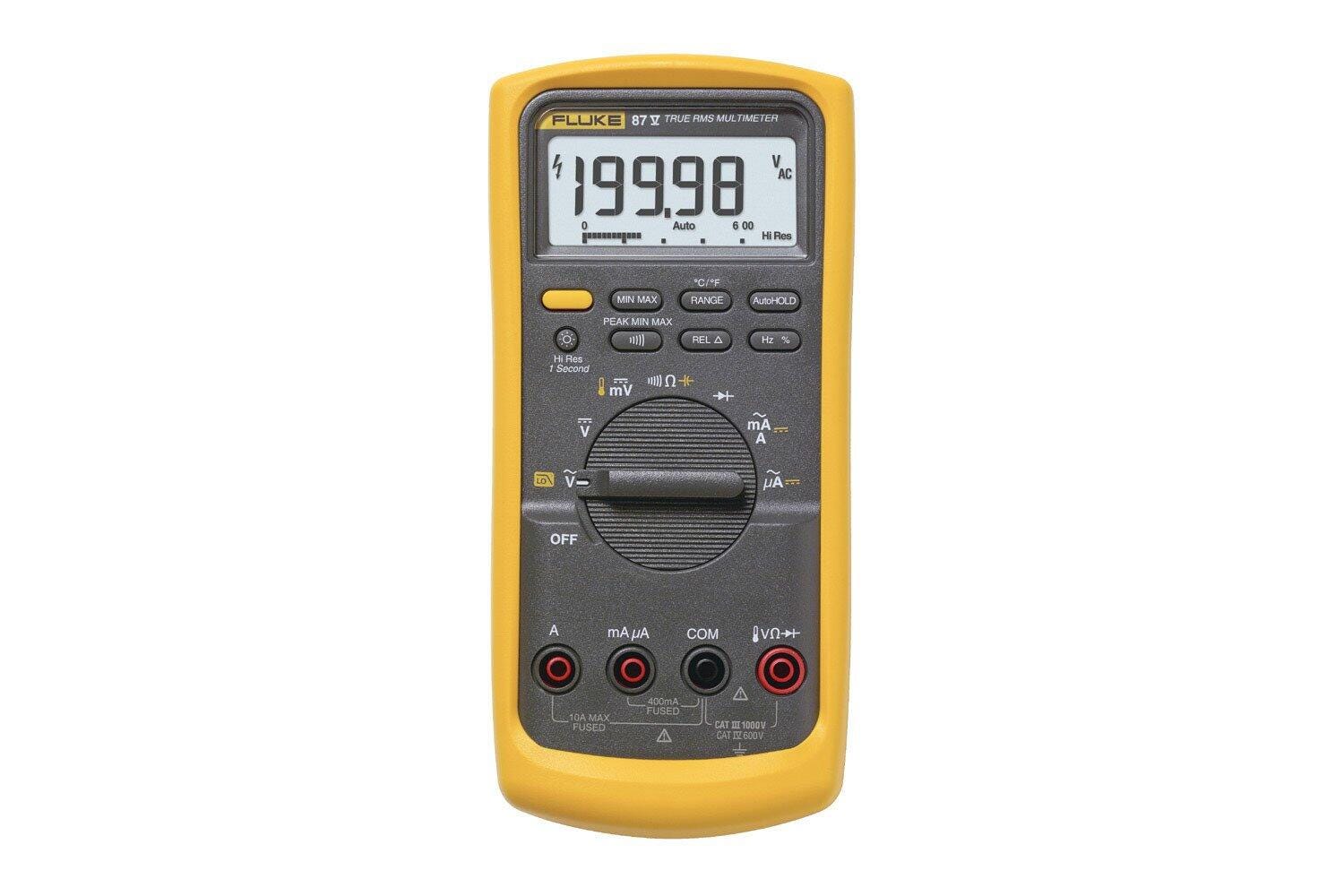
A contract measured at the USB-C link does not establish voltage at a regulator output, motor rail or processor pin. Cable resistance, connectors, protection devices and conversion stages can produce drop or shutdown. Use a multimeter at manufacturer-documented test points to compare input and downstream rails under the real load.
Voltage is measured in parallel. Current measurement normally requires opening the circuit and placing a correctly fused, correctly ranged meter in series; a clamp or dedicated shunt may be safer. Resistance and continuity checks belong on a de-energized circuit. Never put a meter in current mode directly across a voltage source.
A safe diagnostic sequence
- Read the ratings for the source, sink, cable, analyzer, meter and leads.
- Power down before inserting tools or moving probes; identify ground and test points from documentation.
- Use current limiting where the design permits, then energize while watching for abnormal heat, odor or unstable current.
- Save the negotiated contract and link voltage/current.
- Measure documented downstream rails and correlate any reset with both records.
Stop if insulation, connectors or cells are damaged, if exposed contacts cannot be safely fixtured, or if the circuit exceeds the instrument category or rating. The useful diagnosis is a boundary-by-boundary record: requested contract, delivered link behavior and downstream rail response.

That’s a really useful breakdown. It makes a lot of sense that having both a PD tester and a multimeter is crucial for troubleshooting all sorts of power issues – I’m definitely going to keep this in mind.