RTK GNSS is attractive for small field robots because the headline promise is simple: centimeter-level outdoor positioning without painting lines or laying down indoor markers. For mower projects, agriculture prototypes, sports-field robots, and outdoor STEM teams, that sounds like a shortcut to autonomy.
It is not a shortcut. It is a positioning subsystem that needs validation.
Quick answer
Before trusting an RTK GNSS module on a small field robot, validate correction delivery, antenna placement, sky view, repeatability, startup time, loss-of-fix behavior, and how the robot blends GNSS with wheel odometry, IMU data, vision, or safety stops. Centimeter claims only matter if the robot stays safe and repeatable in the actual field.
What RTK adds
Real-Time Kinematic positioning uses correction data to improve GNSS accuracy compared with standalone satellite positioning. u-blox describes RTK as a way to reduce GNSS position error by using correction information from a base station or network service. In robotics terms, RTK can provide a more precise outdoor reference than ordinary GPS.
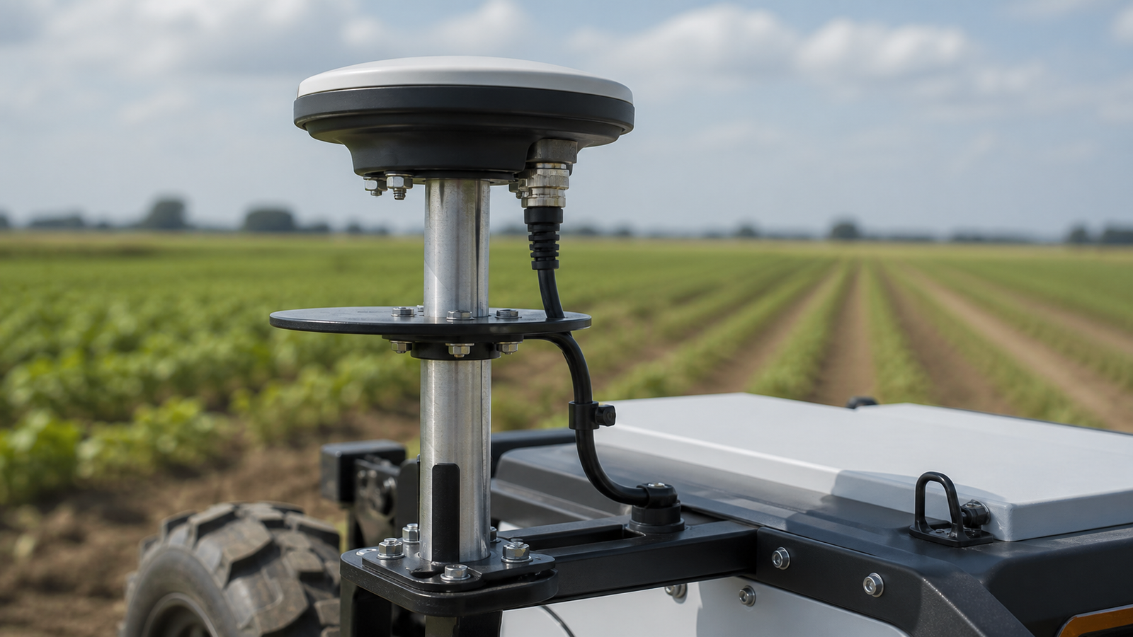
The catch is that the correction link and antenna environment become part of the system. A small robot driving near trees, metal sheds, fences, bleachers, or tall equipment may see accuracy change from one part of the route to another.
Validation checklist
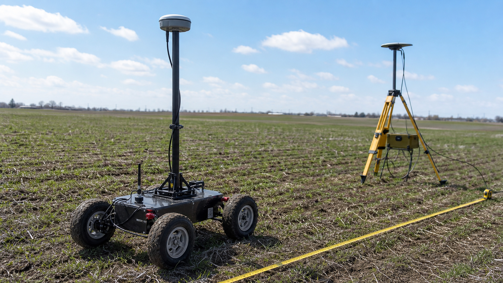
- Correction source: confirm whether the project uses a local base station, NTRIP service, radio link, or another correction path.
- Startup time: measure how long the robot takes to reach a usable fix after power-up.
- Repeatability: drive the same path several times and compare track scatter, not just one good run.
- Antenna mount: keep the antenna stable, high enough for sky view, and away from noisy electronics where practical.
- Loss behavior: define what the robot does when correction drops or accuracy degrades.
- Sensor fusion: do not ask GNSS alone to solve every control problem. Wheel odometry, IMU data, vision, and field boundaries still matter.
Maker and STEM pitfalls
The most common mistake is treating an RTK module as a drop-in replacement for localization engineering. A good module can still produce bad behavior if the antenna is mounted next to a motor controller, the correction link drops at the far side of the field, or the robot continues driving after accuracy degrades.
Another pitfall is testing only in ideal conditions. A sunny open parking lot does not represent a school field with fences, spectators, trees, and temporary equipment. A farm edge or construction site adds its own multipath and safety constraints.
How to structure a first test
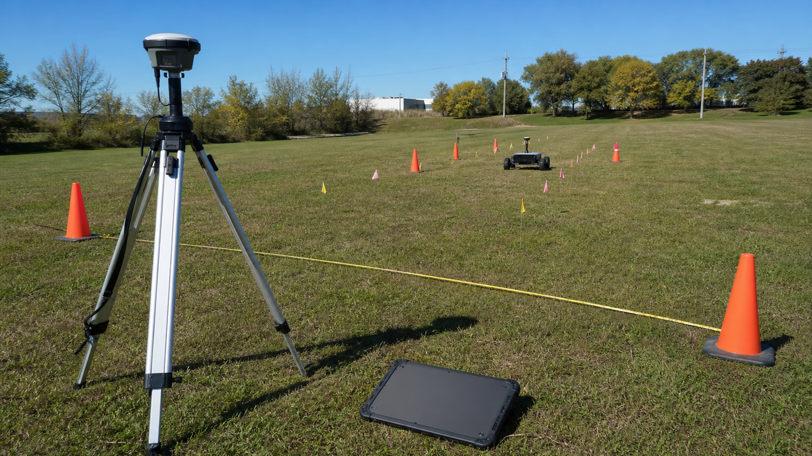
Start with a static test. Place the robot or receiver at a marked point and log position scatter for several minutes. Then run a slow repeated path with physical markers. Only after that should the team test higher speeds, obstacle zones, or autonomy behaviors.
If cameras are part of the stack, pair the GNSS work with calibration discipline. TVG’s robot camera readiness guide is a useful companion because localization and perception errors often look similar during field debugging.
TVG Take
RTK GNSS is powerful for outdoor robotics, but the engineering value is not the marketing phrase “centimeter accuracy.” The value is repeatable position information with known failure modes. For maker teams, that means logging, measured courses, correction-link checks, and conservative fallback behavior before any autonomous field work.