Editorial mode: Template B — Analysis / Guide.
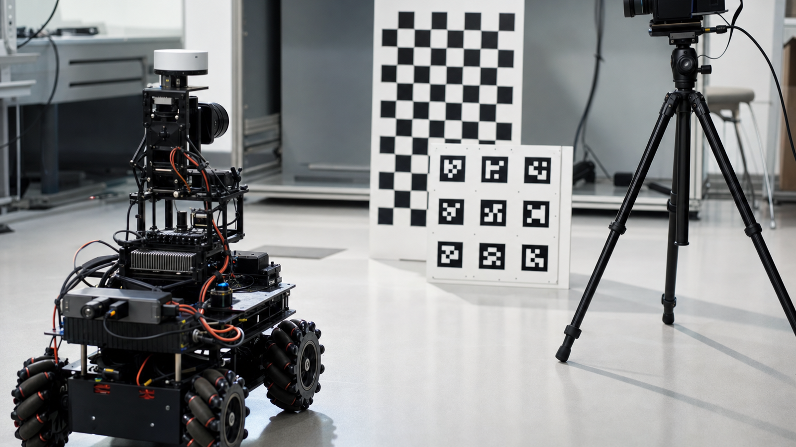
Checkerboards and ArUco markers are familiar tools in robot vision. OpenCV documents camera calibration workflows using images of a known pattern, and ROS camera-calibration tools build on the same practical idea: the robot needs a trustworthy relationship between image pixels and the physical world.
The target matters. But in small labs, bad lighting ruins more calibration sessions than people admit. Glare, motion blur, auto exposure, curled paper and dirty lenses can all produce numbers that look official while making the robot behave worse.
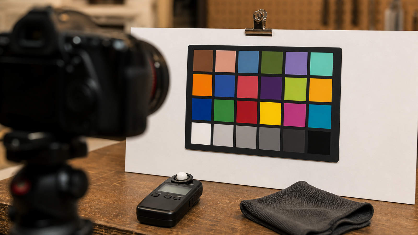
Before capturing images
- Flatten the target: mount the checkerboard or marker board to foam core, acrylic or another rigid backing.
- Kill glare: avoid glossy paper and direct reflections from overhead lights.
- Lock exposure: do not let the camera brighten and darken every frame if the calibration tool allows manual settings.
- Clean the lens: fingerprints can soften corners and confuse edge detection.
- Measure the print: confirm the square or marker size after printing, not just in the PDF file.
Capture more variety, not random variety
Good calibration images cover the field of view: center, edges, corners, tilted angles and different distances. Random waving is not the same as coverage. A quick plan helps: near-left, near-right, far-left, far-right, tilted up, tilted down, rotated, and centered.
For mobile robots, capture images at the working distance the robot will actually use. A camera calibrated only at a desk distance may behave poorly when the robot sees markers across a room or close to the floor.
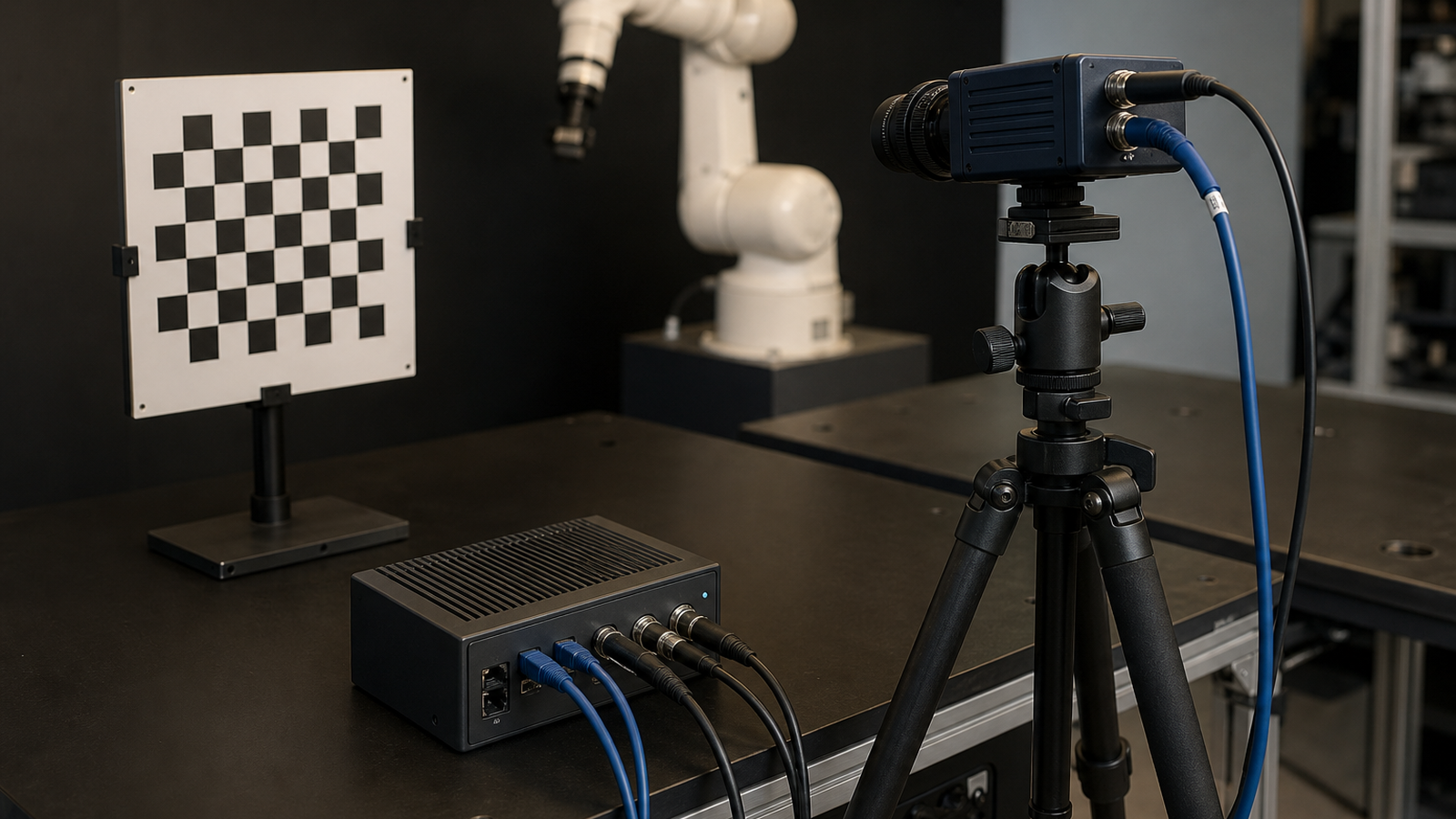
Lighting checklist
Use soft light from the side or front, not a shiny hotspot across the target. Watch the camera preview for blown-out white squares, crushed black squares and shadows crossing corners. If the robot uses the camera under shop lighting, test under shop lighting. If it runs near windows, test with window light changing.
After calibration, validate with a separate board position. Do not celebrate only because the tool produced a file. Move the board, estimate pose, and check whether the result is stable enough for the robot’s job.
TVG Take
Calibration is measurement, not ritual. A checkerboard is useful only when the setup around it is controlled. TVG’s earlier checkerboard calibration guide covers why the target still matters; this lighting checklist is the field note that keeps the numbers honest.
Common failure signs
Bad calibration often shows up as unstable pose estimates, warped overlays, distance estimates that drift across the image, or a robot that behaves correctly in the center of the frame and poorly at the edges. Those symptoms are easy to misread as code problems. Before rewriting the vision pipeline, repeat calibration with better lighting and a flatter target.
Keep a calibration log. Record camera model, lens, resolution, focus setting, target size, lighting setup and tool version. If the robot later changes cameras or lens focus, the old file should not be reused casually. Calibration data is part of the robot configuration, not a generic asset.
Classroom and team workflow
For student teams, assign one person to move the target and another to watch image quality. The observer should reject blurry frames, glare and partial board views before they enter the dataset. That simple division of labor turns calibration from a rushed chore into a repeatable engineering routine.
Teams should also separate calibration from navigation experiments. Capture the calibration dataset while the robot is stationary, the board is flat, and the lighting is controlled. Then use a different session to test motion, vibration and real-world marker detection. Mixing those steps makes it harder to know whether a failure came from camera geometry, lighting, motion blur or the downstream control code.
If the robot uses multiple cameras, calibrate and document each one separately. A wide-angle navigation camera, an arm-mounted inspection camera and a driver-view camera can have different lenses, focus points and distortion profiles even when they share the same sensor family.