Power injection does not create extra power. It adds another low-resistance path from a correctly sized supply to points along an LED strip. The technique can reduce voltage drop and color shift on long runs, but it also creates parallel current paths that must be designed rather than improvised.
Measure the failure before adding wires
Set a known brightness and pattern, then measure voltage at the supply, strip input and far end while the strip is operating. A dim or discolored far end can indicate conductor loss, but a weak supply, undersized connector or overheated joint can produce similar symptoms. Record current and temperature; do not diagnose by color alone.
Build one power budget
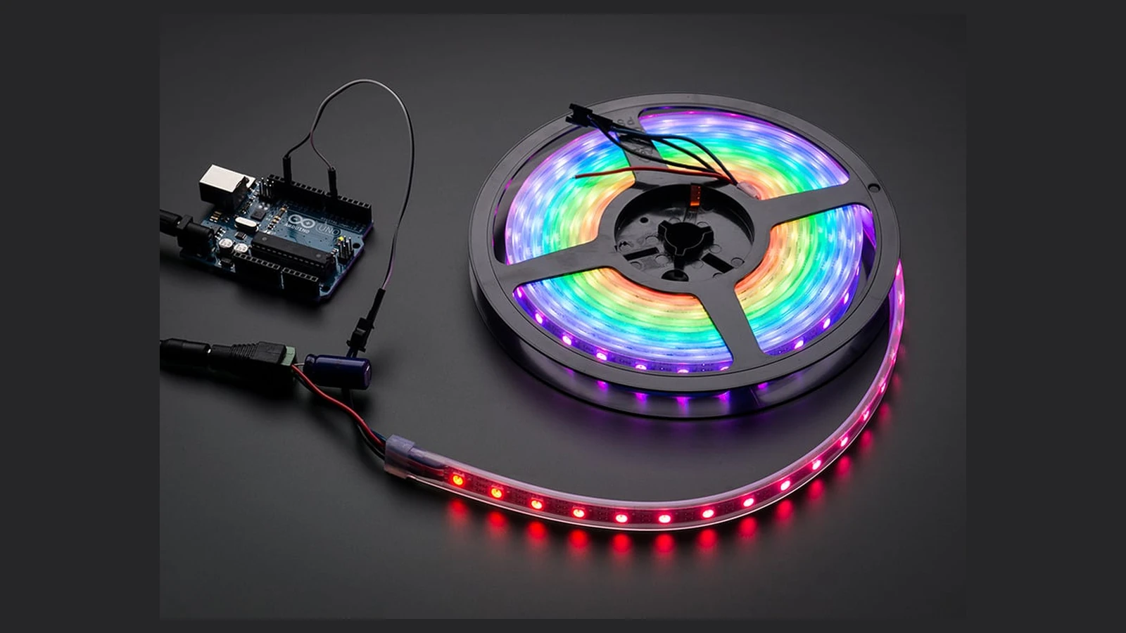
Adafruit’s NeoPixel guidance recommends estimating worst-case current and using a regulated supply appropriate for the project. The supply must cover the intended load with margin, while each wire, connector and branch must be rated for the current it can carry. A larger supply does not make thin conductors safer.
Injection is a parallel feed
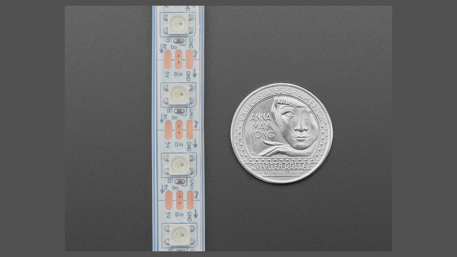
Connect positive and ground at the chosen strip point using verified polarity. Keep controller ground and strip ground common when the data interface requires it, but avoid accidentally tying together incompatible positive outputs from separate supplies. If more than one supply is used, define exactly where positive rails are isolated and how grounds are managed.
Put protection near the energy source
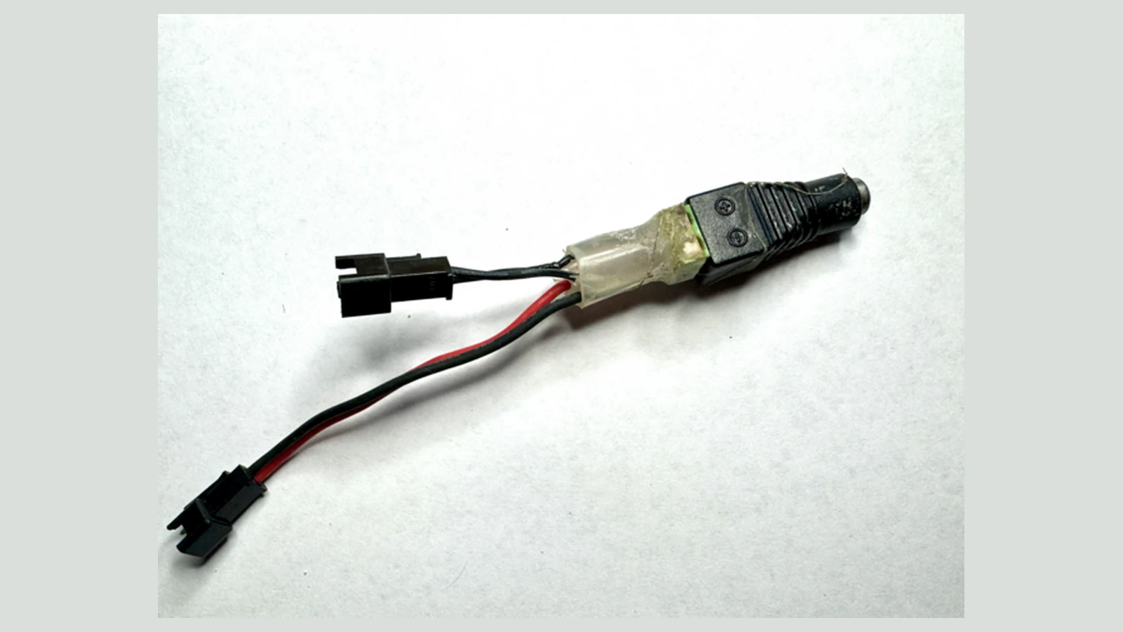
Fusing should protect branch wiring, not merely the power supply. Place appropriate protection near the source so a downstream short cannot turn a long cable into a heater. Use insulated joints, strain relief and enclosures where connectors can be touched or pulled. The photographed splitter is a source example, not proof of its current rating or a universal wiring plan.
Commission one section at a time
Power off before changing connections. Check resistance for an obvious short, verify polarity, energize at a conservative brightness and watch connector and wire temperature. Then repeat the voltage measurements at the operating pattern. Stop if a joint heats, insulation softens or the supply cycles.
Power injection is successful when measured end voltage improves without creating hidden branch or connector overload. Document supply voltage, fuse values, wire gauge, connector ratings and injection locations so the installation can be serviced safely.
Label every branch at both ends and keep a simple as-built sketch beside the supply. Future repairs should not depend on wire color or memory.