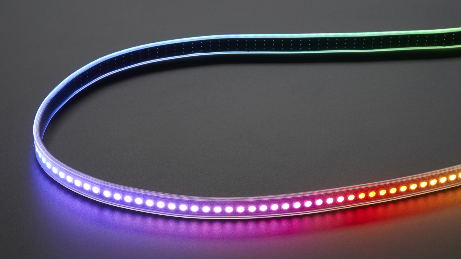
Random colors, a frozen first NeoPixel, or a strip that works only when the LED supply is lowered can come from inadequate logic-level margin. The cited WS2812B datasheet specifies VIH(min) = 0.7 × VDD. At a 5.0 V pixel supply, that is 3.5 V—above a nominal 3.3 V GPIO high.
Featured image: Adafruit.
A 3.3 V controller may appear to work on one strip, cable length, temperature, or power setting, but that does not create guaranteed margin. Fix the electrical boundary before adding delays or repeatedly changing animation code.
Calculate the threshold at the pixel’s actual supply
The threshold follows the LED’s VDD, not the microcontroller’s supply. Using the datasheet relationship:
VIH(min) = 0.7 × VDD
At VDD = 5.0 V: VIH(min) = 3.5 V
At VDD = 4.5 V: VIH(min) = 3.15 V
This explains why lowering the pixel rail can make a marginal 3.3 V signal appear reliable: the input threshold moves down. It is a diagnostic clue, not a reason to run outside the LED and project’s intended power design.
Translate the signal near the controller
A 74AHCT125 is a useful one-way buffer for this job. Powered at 5 V, its AHCT input threshold accepts a 3.3 V logic high while the output drives toward the 5 V domain. Tie the relevant output-enable input active and route the translated output to the first pixel’s data-in pad—not data-out.
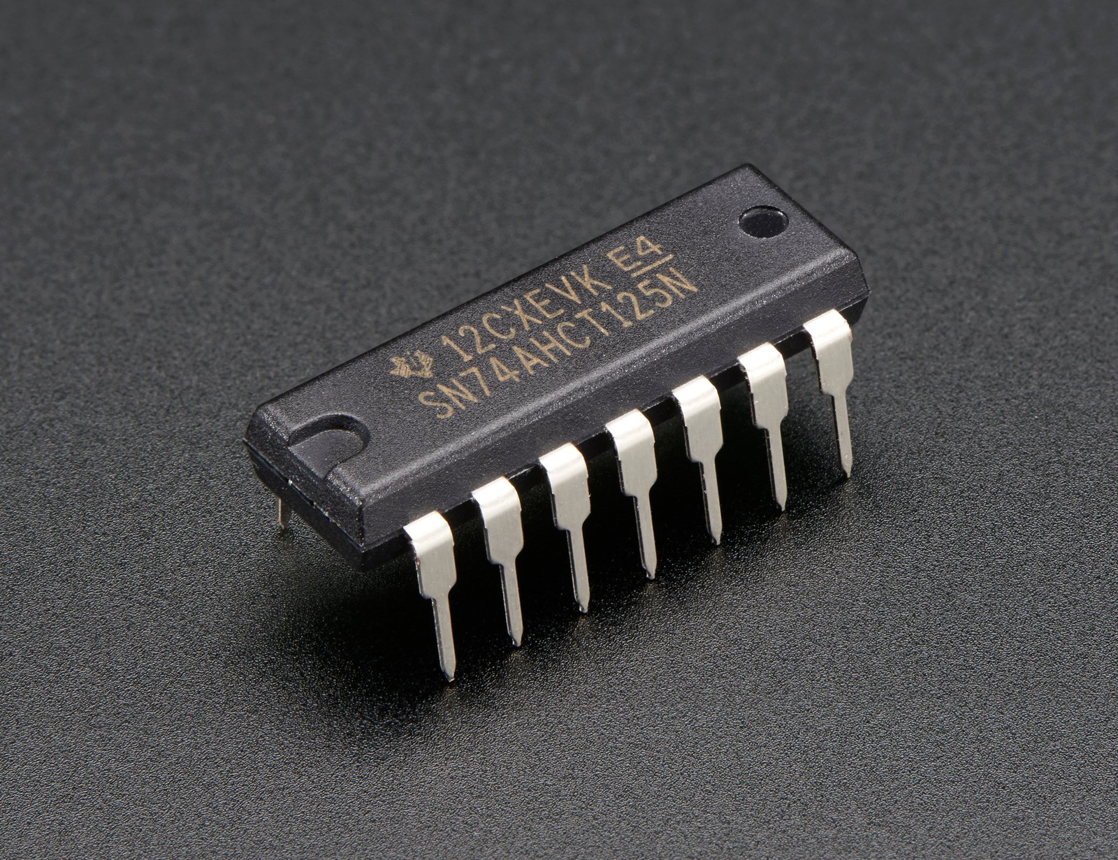
The buffer does not replace a common reference. Connect controller ground, buffer ground, and pixel ground. If those nodes move relative to one another under LED current, the receiver sees less effective signal margin even when the oscilloscope reports an acceptable voltage against the wrong ground point.
Treat the first data edge and the power rail separately
Adafruit’s integration guide recommends a 300–500 Ω resistor in series with the data line at the first pixel. Place it near that input. Its role is edge control and input protection; it is not a substitute for level translation when the high level itself is below specification.
For larger installations, the same guide recommends 500–1000 µF across the pixel power rails. Bulk capacitance helps absorb current steps, while short, adequately sized power and ground wiring reduces rail drop. These measures address supply transients, not the DC logic threshold.
Read the symptom without overfitting it
- Works at lower LED voltage: suspect logic threshold margin, while confirming the lower rail is permitted.
- Works only with a finger or probe attached: suspect a floating reference, ringing, or marginal edge—not “extra capacitance” as a permanent fix.
- Fails as brightness rises: inspect supply drop and ground bounce alongside logic level.
- Only the first pixel misbehaves: verify data direction, the first connection, series resistor placement, and the first device before rewriting the whole pattern.
A scope measurement at the first pixel should reference the pixel ground and capture the data high level while the LEDs are active. That complements the broader power-rail noise workflow; a logic analyzer can confirm bit timing but usually cannot prove analog noise margin.
The reliable repair is therefore ordered: establish a common ground, verify the pixel rail, translate 3.3 V data into the 5 V logic domain, then tune edge control and power distribution. Code becomes the primary suspect only after those electrical conditions are inside specification.