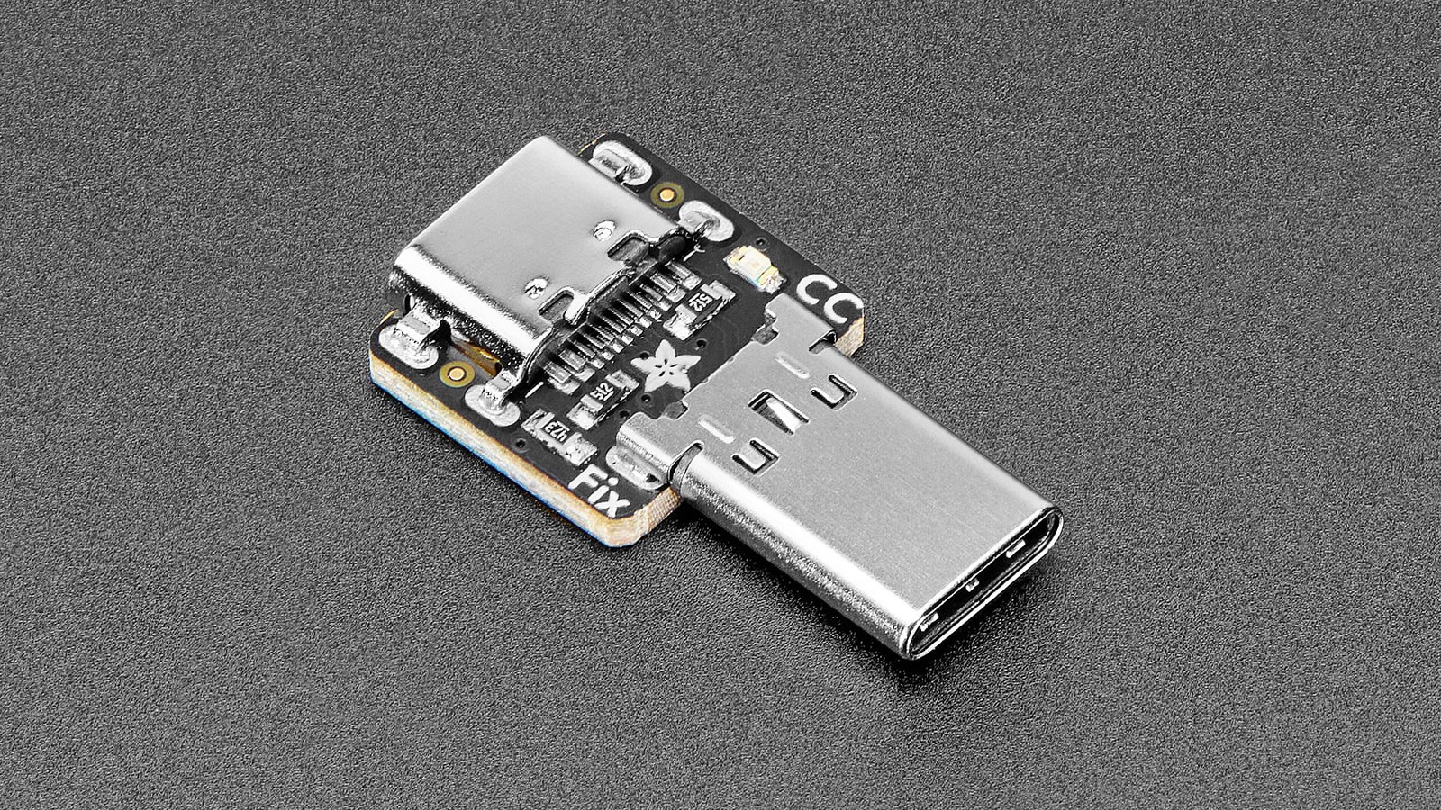
If a USB-powered board starts from a USB-A-to-C cable but remains dead on a USB-C-to-C supply, inspect the receptacle’s configuration-channel network before blaming USB Power Delivery. A simple Type-C sink needs an Rd pull-down on both CC1 and CC2. Without that attach signal, a compliant C source can leave VBUS off.
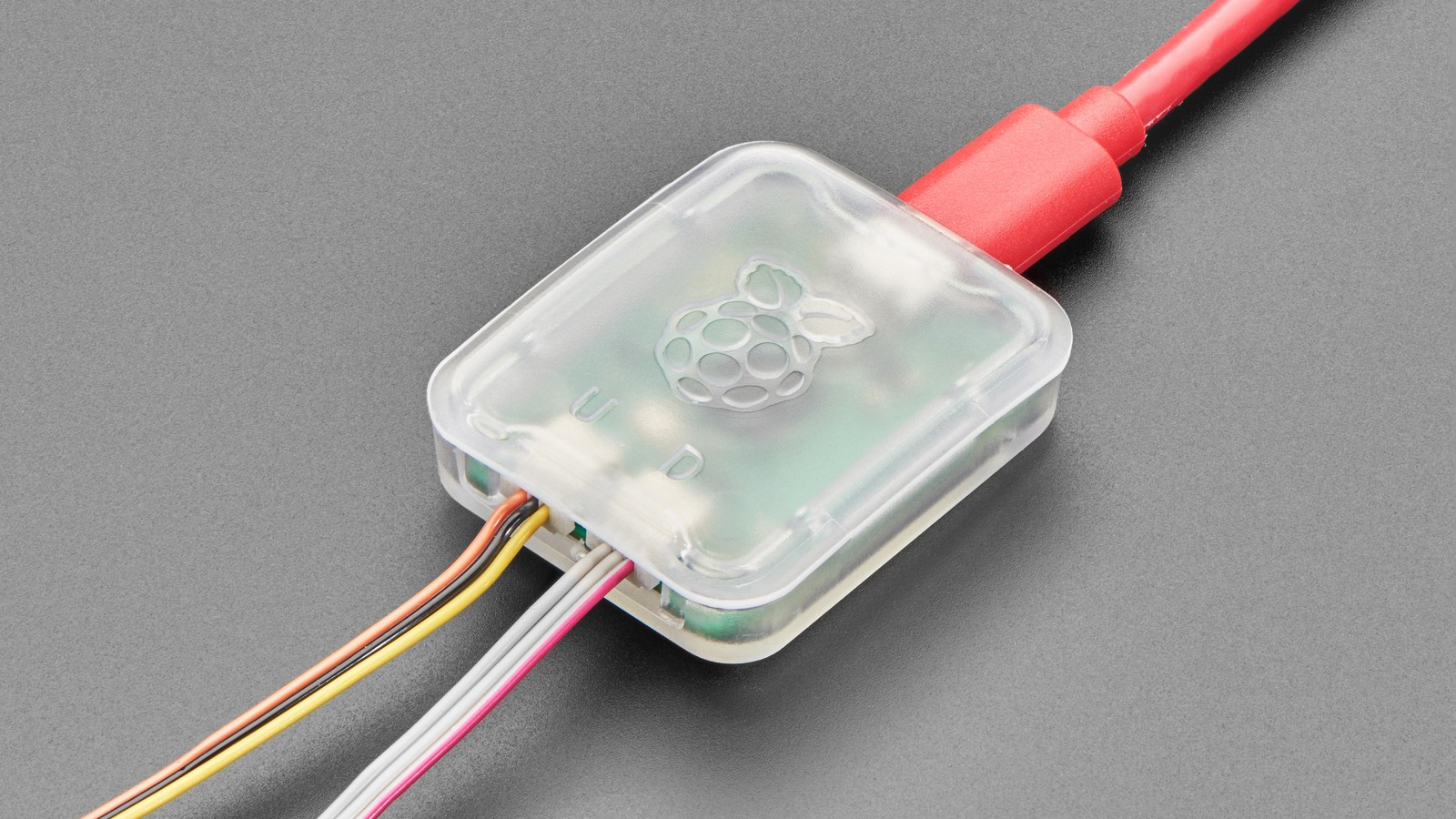
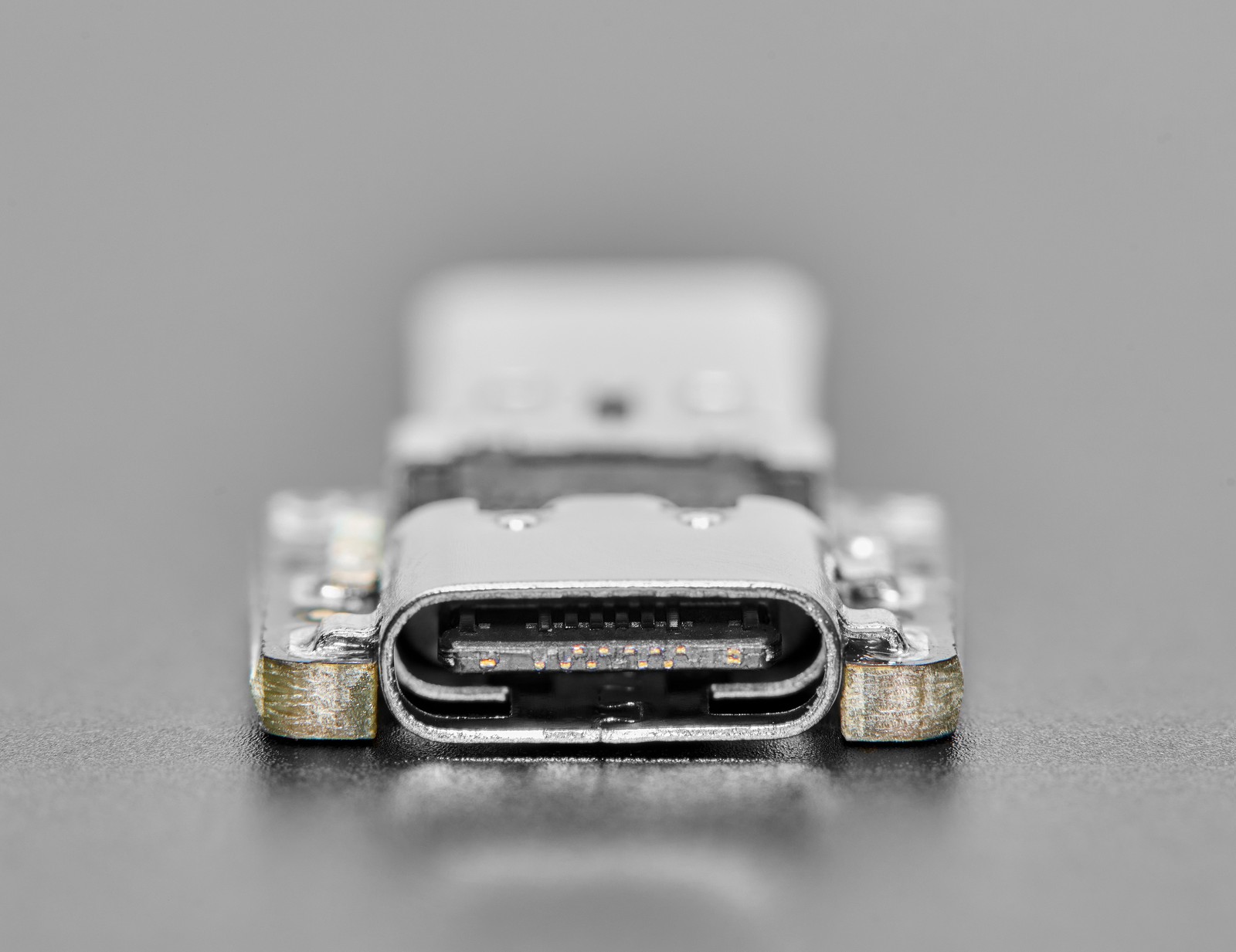
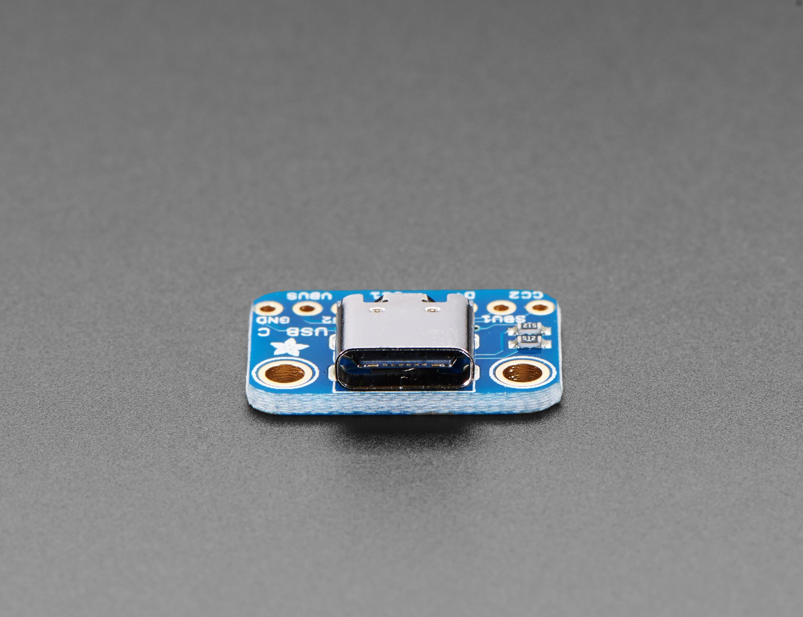
Featured image: Adafruit.
The usual passive implementation is one nominal 5.1 kΩ resistor from CC1 to ground and another from CC2 to ground. The two resistors are not duplicates for extra current capacity. A reversible plug connects one configuration channel according to orientation, so the receptacle must be ready on either contact.
Why the A-to-C cable hides the defect
A legacy USB-A source already exposes 5 V VBUS. The A-to-C cable identifies the source side and can power a load even when the device’s Type-C receptacle is missing its own Rd network. A C-to-C source instead uses the CC pins to detect a valid sink attachment before it enables power.
That creates a useful symptom split. “Works on A-to-C, fails on C-to-C” points toward CC attach detection. It does not prove the power supply is incompatible, and it does not automatically mean the board needs a USB-PD controller.
Use plug orientation as a channel test
If the device works with a C-to-C cable in only one plug orientation, stop rotating connectors at random and trace CC1 and CC2 separately. One pull-down may be absent, open, connected to the wrong net, or isolated by an incorrect footprint. Confirm continuity from each receptacle CC pad through its own resistor to ground.
With power removed, measure the resistance from CC1 to ground and CC2 to ground. A simple passive sink should show the intended Rd path on each. In-circuit readings can be influenced by other components, so compare both channels and use the schematic and component datasheets rather than treating a handheld meter value as a compliance test.
Do not confuse default Type-C power with USB-PD
The CC network first establishes attachment and orientation. It also lets the source advertise available Type-C current. A higher-voltage USB Power Delivery contract is a later protocol step. A board that only needs default 5 V can be a valid Type-C sink without a PD controller, but it still needs correct CC termination.
Conversely, adding a PD trigger board is appropriate when the load needs a negotiated rail such as 9 V, 12 V, 15 V, or 20 V. It is not the first repair for a 5 V board whose receptacle never announces itself as a sink.
A short fault-isolation order
- Confirm the failure with a known-good C-to-C cable and source.
- Try both plug orientations at the device receptacle.
- With power removed, inspect and measure the CC1-to-ground and CC2-to-ground paths.
- Verify that the parts fitted are Rd pull-downs, not source-side Rp pull-ups.
- Only after attach works, examine advertised current, cable capability, and any required PD contract.
For high-current paths, the cable’s e-marker and conductor capability matter too. That is a different boundary from whether the source turns on default VBUS at all.