When esptool reports Wrong boot mode detected (0xXX), the ESP32 has answered over serial, but its reset-time straps did not select the ROM download path. On the original ESP32, verify GPIO0 and EN first; changing upload speed does not correct a chip that booted from flash.
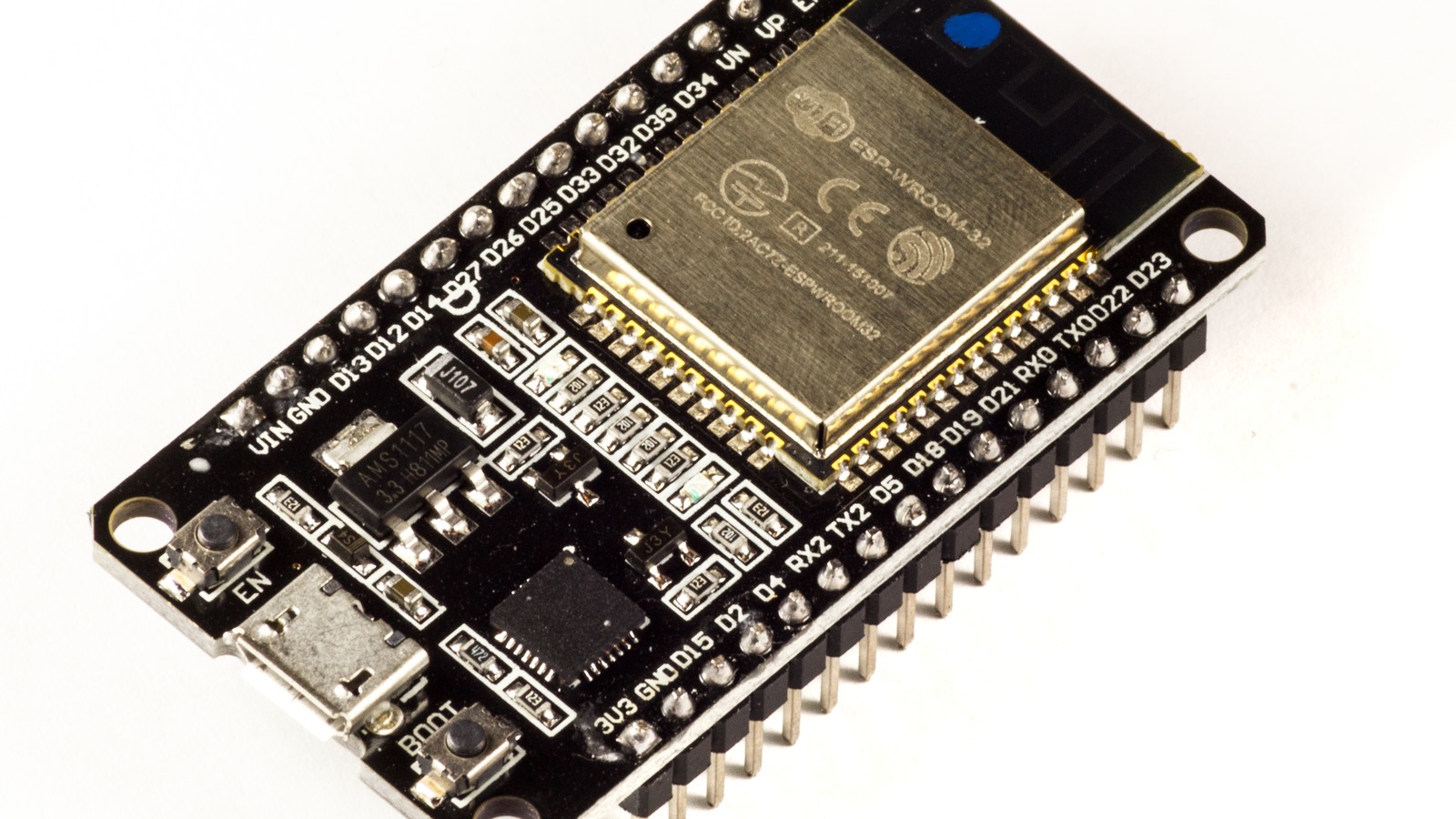
This guide targets the original ESP32 and ESP-WROOM-32 style boards, including DevKitC-class designs. Do not transplant every strap rule to an ESP32-S2, S3, C3, C6 or other family member without checking that chip’s documentation.
Read the ROM line before changing hardware
Disconnect the serial monitor, open the correct port at 115200 bps, then reset the board once. Espressif documents the second ROM line as a reset-and-boot message containing boot:0xNN. A description containing DOWNLOAD_BOOT means the ROM loader was selected. SPI_FAST_FLASH_BOOT means normal execution from flash.
That observation separates three failures. No serial data received points toward the port, power, USB-UART bridge, RX path or a chip held in reset. Wrong boot mode means a ROM line arrived but the sampled straps selected the wrong path. Download mode detected, but no sync reply shifts suspicion toward the host-to-ESP TX path because the target transmitted but did not receive the esptool request.
Prove manual download mode before debugging auto-reset
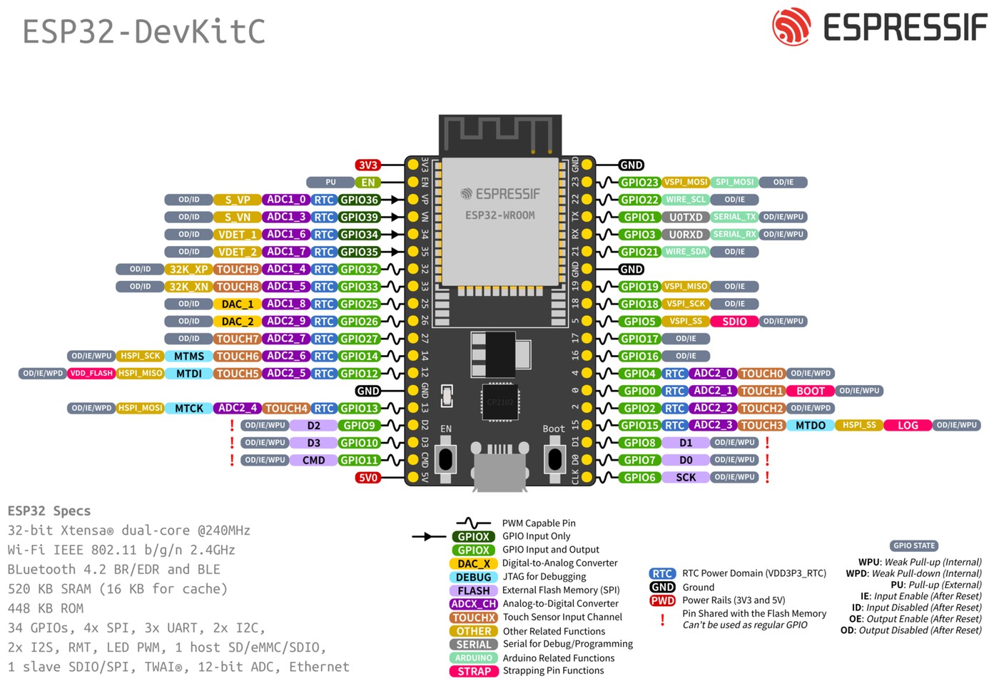
On the original ESP32, GPIO0 low at reset selects the serial bootloader; GPIO0 high selects normal execution. Espressif notes that GPIO0 has an internal pull-up and gives 10 kΩ to ground as an example of a sufficiently strong manual pull-down.
- Remove external circuits from GPIO0, GPIO2, EN and the UART pins.
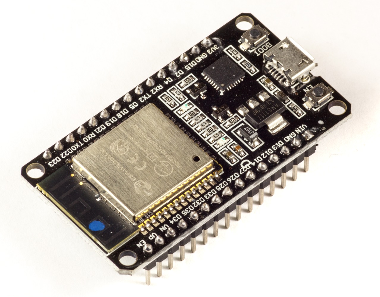
- Hold the board’s BOOT button, which normally pulls GPIO0 low.
- Press and release EN/RESET while BOOT remains held.
- Start esptool or the IDE upload, then release BOOT after the connection begins.
- Capture the 115200-bps ROM line and confirm
DOWNLOAD_BOOT.
GPIO2 must also be floating or low for the original ESP32 serial bootloader. GPIO12 is another dangerous startup load: driving it high selects 1.8 V for VDD_SDIO instead of the default 3.3 V, which can prevent a 3.3 V flash device from operating. GPIO15 low can suppress the ROM boot messages, so silence is not always a dead UART.
If manual entry works, inspect DTR and RTS
A successful manual sequence proves that the ROM loader, GPIO0 strap and EN reset path can work. The remaining failure is often the automatic reset chain. Espressif’s reference arrangement uses active-low USB-UART control signals: RTS drives EN and DTR drives GPIO0 through a two-transistor network that avoids holding the chip in reset when both signals are asserted together.
Check that the IDE has the correct port and that no terminal program owns it. Then observe EN and GPIO0 with a logic analyzer or oscilloscope during an upload attempt. GPIO0 must be low when reset is released, not pulled down later. Espressif specifies a minimum 3 ms hold time after CHIP_PU rises before strap pins return to normal GPIO use.
Espressif’s hardware guidance documents a 1 µF to 10 µF capacitor from EN to ground as part of reliable auto-reset behavior. Some third-party boards omit enough EN capacitance and become timing-sensitive. A practical independent workaround uses 10 µF, but it should follow—not replace—the manual-mode proof and a check for incorrect external loading.
Linux can hold the board in a reset loop
Espressif notes that Linux serial ports may assert RTS by default when opened. If RTS is wired directly or the auto-reset network is incomplete, the board can remain in reset or repeatedly reset. The documented diagnostic is sudo stty -F /dev/ttyUSB0 -hupcl, adjusted for the actual device node, which disables hang-up-on-close behavior for that port.
Do not apply that command to an assumed device name. Confirm the adapter with ls -l /dev/serial/by-id/ or an equivalent stable USB-serial mapping first; the wrong port can make a working board look unresponsive.
Stop when the evidence changes category
- ROM says SPI_FAST_FLASH_BOOT: GPIO0 was not low at reset; inspect the BOOT switch, external loads and reset timing.
- ROM says DOWNLOAD_BOOT but esptool gets no reply: inspect host TX to ESP RX, port ownership and serial integrity.
- No ROM text at 115200 bps: inspect power, EN level, UART wiring and GPIO15 before changing strap resistors.
- Manual entry works but automatic entry fails: inspect DTR/RTS routing, transistor logic, EN capacitance and host control-line behavior.
The decisive test is not whether pressing BOOT “sometimes helps.” It is whether the ROM reports the intended boot mode at the reset edge. Once that line is recorded, GPIO straps, reset control and serial transport become separate, testable boundaries.