RS-485 errors that appear as corrupted first bytes, random packets during silence or failures only at the far end do not all have one cause. Termination controls edge reflections; biasing gives an undriven bus a defined idle state. Diagnose those mechanisms separately before adding resistors, because another terminator can reduce amplitude while another bias network can overload the driver.
Featured image: S.J. de Waard/Wikimedia Commons (CC BY-SA 3.0; cropped to 16:9).
Termination belongs at the cable ends
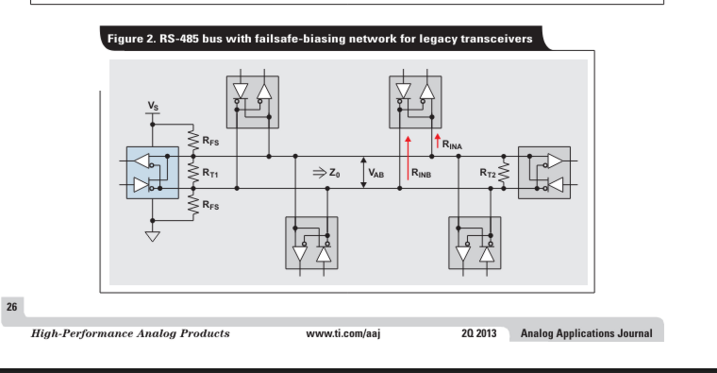
Texas Instruments’ AN-1057 Rev. B explains that parallel termination should match the cable’s characteristic impedance and sit at both ends of the main cable. For common 120-ohm twisted pair, two 120-ohm terminators appear in parallel when power is off, so a resistance measurement across the differential pair near 60 ohms is a useful first check after isolating powered electronics and parallel paths.
A substantially higher reading can mean one end is unterminated or disconnected. A much lower reading can indicate extra termination or another low-resistance path. The exact meter result also includes transceivers, protection and bias components, so treat 60 ohms as a topology clue rather than an acceptance certificate.
Biasing solves silence, not reflections
When every driver is disabled, legacy receivers can interpret a near-zero differential voltage unpredictably. A fail-safe bias network pulls the pair toward a known idle polarity. Modern transceivers such as Analog Devices’ ADM3070E family specify true fail-safe receiver inputs, but a mixed network must be evaluated around the least capable installed receiver rather than the newest part.
Bias resistors form a loaded divider with the termination network. Stronger bias raises the idle differential voltage but increases DC load; weaker bias reduces load but leaves less noise margin. Do not copy a resistor pair without calculating the effective termination, supply tolerance and receiver threshold for the actual bus. Place one intentional bias source unless the system design explicitly accounts for multiple networks.
Use the waveform to tell the mechanisms apart
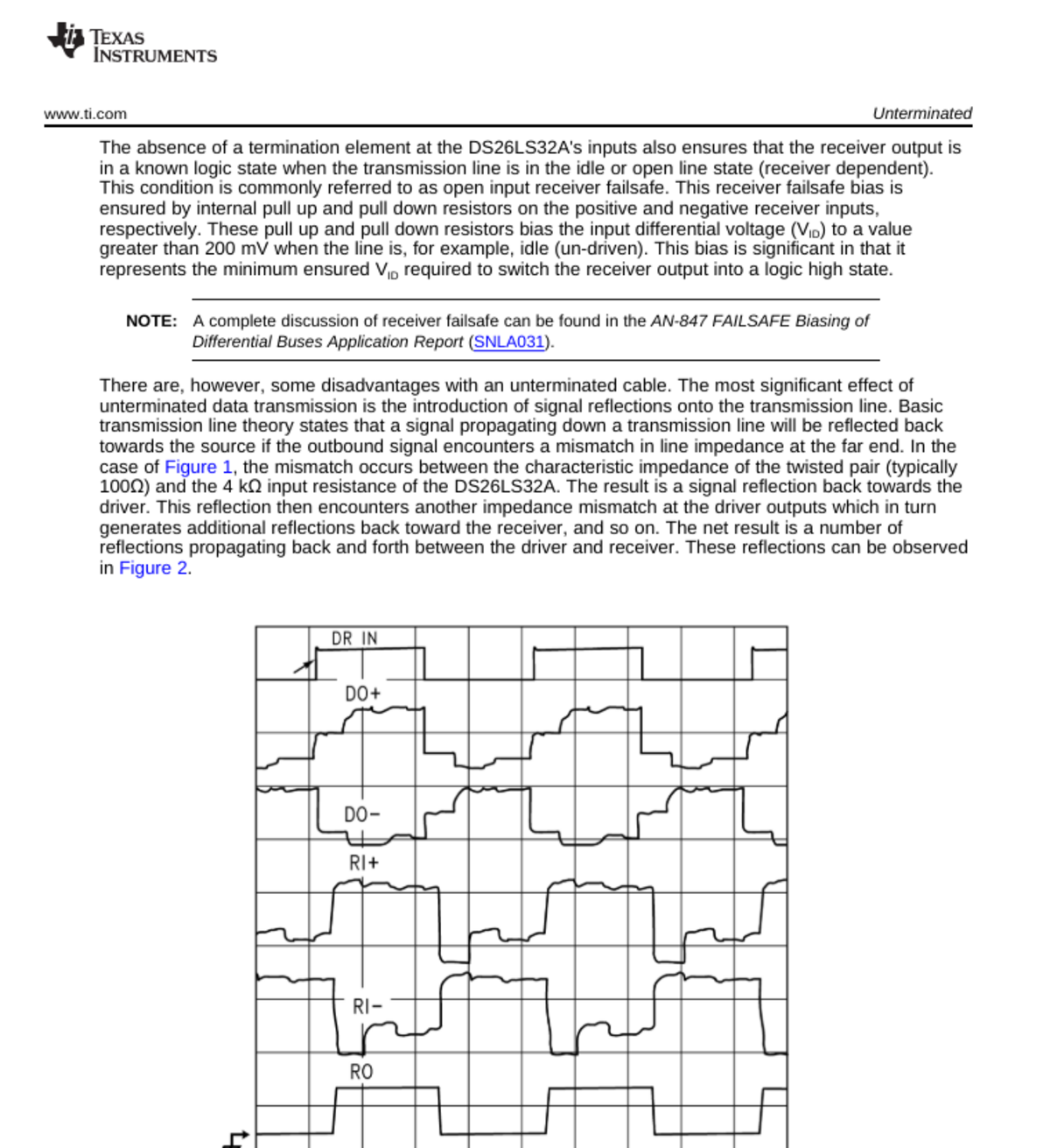
Probe A and B at the same physical point and view the differential trace with a rated differential probe or the oscilloscope’s channel-math function, within the instrument’s grounding limits. Reflection faults follow transitions: overshoot, undershoot or repeated steps appear after an edge and change with cable length, stub length or termination. Idle-bias faults appear between frames: the differential voltage drifts near the receiver decision region when no driver owns the bus.
TI’s note warns that unterminated or poorly terminated lines create reflections, particularly with fast edges and long cables. Stub branches make the problem harder because the edge travels down the branch and returns later. A star may work at low rates or short distances and fail when cable length or transceiver edge speed changes, even though the protocol settings remain identical.
A measured order of operations
- Draw the trunk, both endpoints, every stub and every bias location.
- Power down safely and measure across the pair at one connector; investigate a large departure from the expected parallel termination.
- Power up, capture the idle differential level, then trigger on the first transition of a frame.
- Compare the waveform at both cable ends and at the failing node.
- Change one variable—one terminator, one bias source, one stub or one ground path—then repeat the same capture.
The protocol analyzer belongs after this physical check. Framing or CRC errors show that reception failed, but not whether the cause was a reflection at the sample point, an undefined idle interval, a common-mode excursion or incorrect baud and parity settings.
The decision boundary
If the error clusters around edges and changes with location or cable geometry, work on termination and topology. If false transitions occur during quiet intervals, inspect fail-safe behavior and bias loading. If both differential states remain valid but one node still fails, move up to transceiver enable timing, UART settings and protocol framing.
Waveshare’s USB-to-RS-485 documentation lists an FT232RNL USB bridge, an SP485EEN transceiver, surge and ESD protection, and hardware automatic direction control. Those adapter features cannot correct a trunk with the wrong number of terminations or unmanaged bias sources.
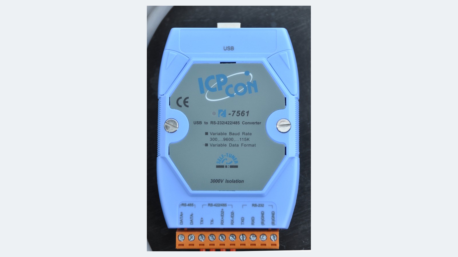
Featured image: “USB to Isolated RS-232-422-485 Converter Make ICP con,” © S.J. de Waard, via Wikimedia Commons, CC BY-SA 4.0. Center-cropped to 16:9 and resized from 2497×3745 to 1600×900 by TVG Report. Source image.